Debug
ARM DDI 0432C Copyright © 2009 ARM Limited. All rights reserved. 6-3
ID112415 Non-Confidential
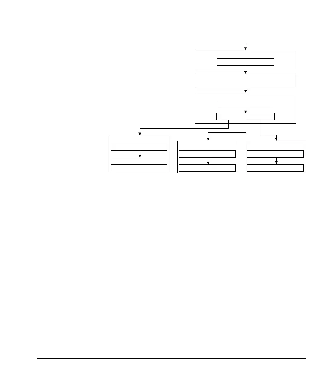
Figure 6-1 CoreSight discovery
To identify the Cortex-M0 processor within the CoreSight system, ARM Limited
recommend that a debugger:
1. Locates and identifies the Cortex-M0 ROM table using its CoreSight
identification. See Cortex-M0 ROM table identification values on page 6-4 for
more information.
2. Follows the pointers in that Cortex-M0 ROM table:
a. System Control Space (SCS)
b. Breakpoint unit (BPU)
c. Data watchpoint unit (DWT).
See Cortex-M0 ROM table components on page 6-4 for more information.
When a debugger identifies the SCS from its CoreSight identification, it can
identify the processor and its revision number from the CPUID register offset at
0xD00
in the SCS,
0xE000ED00
.
A debugger cannot rely on the Cortex-M0 ROM table being the first ROM table
encountered. One or more system ROM tables are required between the access port and
the Cortex-M0 ROM table if other CoreSight components are in the system, or if the
implementation is uniquely identifiable.
CoreSight debug port
Cortex-M0 ROM table
CoreSight ID
Pointers
CoreSight access port
Base pointer
System control space
CoreSight ID
Cortex-M0 CPUID
Debug control
‡Data watchpoint unit
CoreSight ID
Watchpoint control
‡Breakpoint unit
CoreSight ID
Breakpoint control
‡ Optional component
Redirection from the
‡
System ROM table, if implemented