Programmers Model
ARM DDI 0363G Copyright © 2006-2011 ARM Limited. All rights reserved. 3-9
ID073015 Non-Confidential
3.6 Program status registers
The processor contains one CPSR and five SPSRs for exception handlers to use. The program
status registers:
• hold information about the most recently performed ALU operation
• control the enabling and disabling of interrupts
• set the processor operating mode.
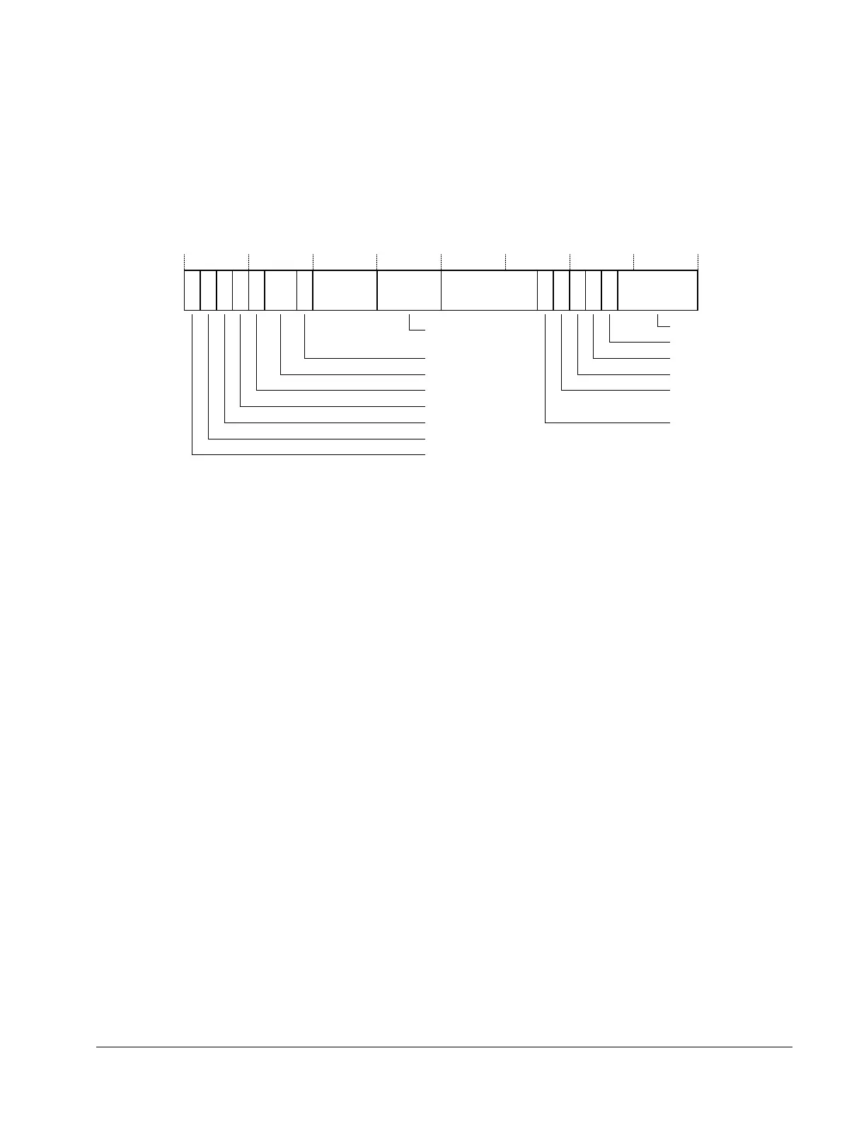
Figure 3-4 shows the program status register bit assignments.
Figure 3-4 Program status register bit assignments
The following sections explain the meanings of these bits:
• The N, Z, C, and V bits
• The Q bit on page 3-10
• The IT bits on page 3-10
• The J bit on page 3-11
• The DNM bits on page 3-11
• The GE bits on page 3-11
• The E bit on page 3-12
• The A bit on page 3-12
• The I and F bits on page 3-12
• The T bit on page 3-12
• The M bits on page 3-13.
• Modification of PSR bits by MSR instructions on page 3-13.
3.6.1 The N, Z, C, and V bits
The N, Z, C, and V bits are the condition code flags. You can optionally set them with arithmetic
and logical operations, and also with
MSR
instructions and
MRC
instructions to R15. The processor
tests these flags in accordance with an instruction's condition code to determine whether to
execute that instruction.
In ARM state, most instructions can execute conditionally on the state of the N, Z, C, and V bits.
The exceptions are:
•
BKPT
•
CPS
•
LDC2
•
MCR2
•
MCRR2
M[4:0]TFIAEIT[7:2]GE[3:0]NJ
Greater than
or equal to
Java state bit
Sticky overflow
Overflow
Carry/Borrow/Extend
Zero
Negative/Less than
Mode bits
Thumb state bit
FIQ disable
IRQ disable
Imprecise abort
disable bit
Data endianness bit
31 30 29 28 27 26 25 24 23 20 19 16 15 10 9 8 7 6 5 4 0
ZCVQ
IT[1:0]
DNM