4 G12 OEM Board & Sensor Reference Manual
connecting a 3 to 3½-volt external battery to the appropriate pins on J301. The
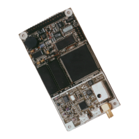
physical dimensions of the G12 GPS board are shown in Figure 1.1.
From a functional point of view, the G12 receiver consists of two major sections:
The radio frequency (RF) section, and the digital section, where the signals from
the GPS satellites are processed.
Both versions of the G12 have two RS-232 input/output (I/O) ports capable of
two-way communication with external equipment, and a coaxial RF port for the
antenna.
The RF section receives satellite signals from the GPS antenna and LNA through
a coaxial cable, and also supplies power to the antenna/LNA through the cable,
eliminating the necessity of a separate power cable for the antenna. Total power
consumption (including the LNA) is approximately 2.1 watts for the board and 2.5
watts for the sensor.
The twelve-pin connector (J101) on the side of the board is intended for factory use only.
The G12 uses a standard SMA connector for RF input (Figure 1.1). A straight-up
OSX RF connector is also available as an option.
A two-color LED is mounted on the G12: Red indicates the power status, and
green indicates the number of satellites locked (e.g., 4 green flashes indicate 4
satellites locked).
G12RevD.book Page 4 Tuesday, April 2, 2002 4:33 PM