Getting Started 21
Getting Started
1. Connect the female plug on the power cable to the J301 male connector on
the G12 before applying power.
2. Connect the power cable to the power supply.
Applying power to the G12 starts the unit. Once power is connected, the two-
color LED on the G12 GPS board flashes red.
Antenna
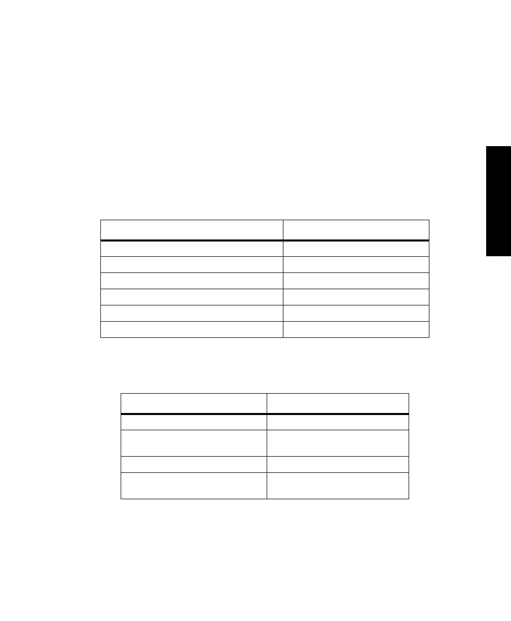
The G12 is designed to work with an antenna Low Noise Amplifier (LNA) that
requires five volts and is isolated from DC ground. The gain of the antenna LNA
minus the loss of the cable is between 20 and 30 dB. Table 1 defines the antenna
requirements.
Table 2 defines the antenna LNA requirements
Table 2.1. Antenna Requirements
Requirement Parameter
GPS operational band 1575 ±10 MHz
Polarization type Right hand circular
Axial ratio Less than 3 dB in zenith of up area
Antenna gain for elevation angle of 10° No less than -2.5 dB
Antenna gain for elevation angle greater than 15° -1 to -2 dB
Antenna gain for elevation angle of 90° ~ +4 dB
Table 2.2. Antenna LNA Requirements
Requirement Parameter
Impedance of antenna output 50W VSWR <1.8
LNA gain Antenna/LNA gain minus cable loss:
between 20 and 30 dB
Noise figure < 4.0 dB
LNA selectivity -3 dB bandwidth: 35 MHz
-20 dB bandwidth: 60-70 MHz
G12RevD.book Page 21 Tuesday, April 2, 2002 4:33 PM