10 G12 OEM Board & Sensor Reference Manual
2. Manual reset (MAN_RES*) should be left unconnected if unused. Manual
reset should be activated by a switch or open collector gate.
3. Magellan internal use only (leave floating).
The operating temperature range of the G12 is -30°C to +70°C; storage
temperature range is -30°C to +85°C.
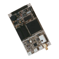
A 50-ohm coaxial cable and an LNA are required for impedance matching
between the G12 RF connector and the GPS antenna. The G12 board’s RF
connector is a standard SMA female connector (TNC on the G12 Sensor, see
Figure 1.4). The SMA connector shell is connected to common ground on the
G12 board. The SMA center pin provides +4.8 VDC (to power the LNA) and
accepts 1575 MHz RF input from the antenna; the RF and DC signals share the
same path. The gain of the antenna LNA minus the loss of the cable is in between
20 and 30 dB.
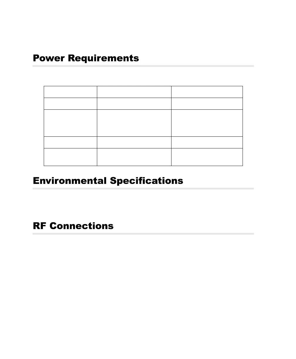
Table 1.3. Power Requirements
Requirement Board Sensor
DC voltage
5 volts DC, regulated ± 5% 9 - 36 VDC
Power Consumption
(typical)
1.8 watts
(2.1 watts with antenna/LNA)
Current draw: 360 mA @ 5 VDC
2.2 watts
(2.5 watts with antenna/LNA)
Current draw: 245 mA @ 9 VDC
61 mA @ 36 VDC
External wiring
30 gauge (minimum) 30 gauge (minimum)
Internal battery drain
1
mA (without 5 VDC applied)
0.3
mA (with 5 VDC applied)
1
mA (without 9-36 VDC applied)
0.3
mA (with 9-36 VDC applied)
G12RevD.book Page 10 Tuesday, April 2, 2002 4:33 PM