22 G12 OEM Board & Sensor Reference Manual
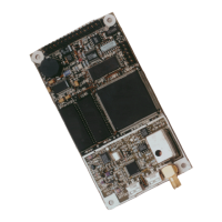
Connect the antenna cable directly to the antenna SMA connector on the G12.
Once power is on and the antenna is connected, the G12 acquires satellites (SVs
or Space Vehicles) within the field of view of the antenna. As a channel in the
G12 locks on to a satellite, the two-color LED flashes green between the red
power flashes for every channel in use (i.e., locked satellites).
Communication Port Setup
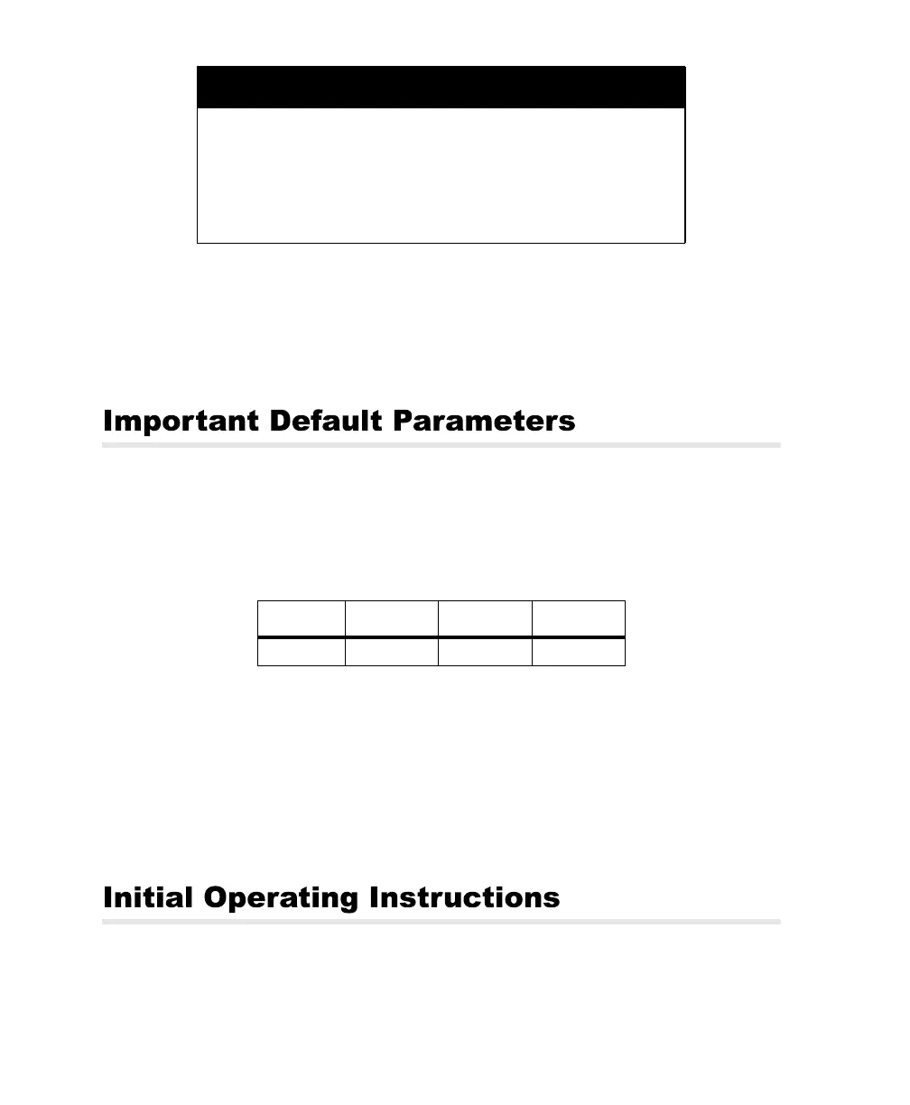
Table 3 lists the default communication parameters of the G12:
When first establishing communications with the G12, the communications
interface must use this protocol.
Data Output Options
All the default data output commands are set to OFF. The G12 does not output
any data until you command it to do so.
After the G12 is powered and running, you must send it command messages in
order to receive data (such as antenna position). The following procedure
CAUTION
The G12 may be damaged if the center pin of the RF connector (Type
SMA) is not isolated from DC ground. Provide a DC block between
the center pin and ground; the DC block should have the following
characteristics:
• VSWR 1.15 maximum at 1575 MHz
• Insertion loss 0.2 dB maximum
• Maximum voltage 5 VDC
Table 2.3. G12 Communication Parameters
Baud Data Bits Parity Stop Bits
9600 8 None One
G12RevD.book Page 22 Tuesday, April 2, 2002 4:33 PM