Do you have a question about the ashtech G12 and is the answer not in the manual?
Details the G12 GPS receiver's functionality, including signal processing, channel capabilities, and operational modes.
Explains the G12's built-in self-test, memory initialization, satellite tracking, and position computation capabilities.
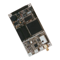
Describes the G12 receiver in two versions (Sensor and OEM Board), detailing power, enclosure, and component specifications.
Details the J301 connector for all power and input/output connections, including pin assignments.
Provides a detailed table of pin assignments for the J301 connector on the G12 OEM board.
Illustrates the connections between the G12 board and external equipment via the J301 connector.
Lists the DC voltage, power consumption, and wiring gauge requirements for the G12 board and sensor.
Specifies the operating and storage temperature ranges for the G12 receiver.
Describes the RF connector and impedance matching requirements using a coaxial cable and LNA.
Advises on potential interference from radio transmitters and recommends verifying nearby devices.
Explains how receiver options determine available commands and features, listing common options.
Describes the lower-cost G12-L version with reduced update rates and multipath mitigation features.
Lists and describes the G12 Sensor and G12 OEM Board Evaluation Kits available for purchase.
Details how G12 firmware is stored, loaded, and updated, recommending external serial port design.
Provides instructions on connecting the G12 to power, antenna, and controller devices via the J301 connector.
Explains how to apply power to start G12 operation and how removing power stops it.
Details antenna requirements, including operational band, polarization, and gain specifications.
Lists the default communication parameters for the G12 serial ports.
Explains the default communication parameters and protocol required for establishing communication.
States that all default data output commands are OFF and data is only output when commanded.
Guides on sending command messages to the G12 to receive data such as antenna position.
Covers setup requirements, including compliance with hardware specifications for non-Magellan equipment.
Describes the status LED behavior during power-up and satellite lock indication.
Explains the structure and format of messages received and sent by the G12 via RS-232 ports.
Details the format of input messages, including NMEA 0183 compliance and Ashtech proprietary deviations.
Describes the types of output messages (status, ACK/NAK, GPS data) and their compliance with NMEA standards.
Explains the default serial port protocol (9600 baud, 8N1) and how to adjust it using commands.
Describes the satellite search process, almanac/ephemeris data collection, and position computation.
Details how to query general receiver parameters and the default settings after initialization.
Explains how to save new parameter settings using the $PASHS,SAV,Y command.
Describes the watchdog timer's function to reset the receiver if the processor hangs up.
Details the four position computation modes (0-3) that determine satellite requirements and output.
Defines two modes for altitude setting when the G12 is in altitude hold mode.
Specifies the geoid model used (OSU91A) and provides OSU contact information.
Explains the use of ionospheric and tropospheric models for error compensation in autonomous mode.
Identifies the Joint US/UK 1995 Epoch World Magnetic Model (WMM-95) used by the G12.
Describes how to enter accurate antenna position for differential base mode calculations.
Details the output of NMEA and Ashtech NMEA-style messages, including compliance and length variations.
Explains the optional feature to output raw data (MBN, PBN, SNV, SAL, MCA) in binary format.
Discusses real-time differential operation concepts, commands, and RTCM-SC104 correction messages.
Identifies major sources of GPS range measurement errors and how they are mitigated.
Explains RTCM message formats for differential corrections and G12 support for various RTCM types.
Details RTCM message types 1, 2, 3, 6, 9, and 16 used for differential corrections.
Describes how to measure and record events with high accuracy using a photogrammetry trigger signal.
Explains using the camera shutter signal for accurate time-tagging of pictures with GPS observations.
Combines PPS synchronization and shutter timing for accurate event time tagging.
Details the TTL-level timing pulse output synchronized with GPS time.
Explains optional capabilities for 10 Hz or 20 Hz internal update rates for position and raw data.
Describes Receiver Autonomous Integrity Monitoring for detecting anomalous satellite pseudorange errors.
Lists and defines symbols used to represent parameter types in ASCII message structures.
Explains commands for changing or querying receiver operating parameters and status.
Defines the format for query messages, including headers, message identifiers, and optional parameters.
Details the command to set Receiver Autonomous Integrity Monitor modes and alarm limits.
Explains the command to set the ellipsoidal height of the antenna for 2D position computations.
Describes the command to query the real-time clock status and its response format.
Explains the command to select the code correlator type for multipath mitigation.
Details the command to enable or disable CTS/RTS handshaking protocol on serial ports.
Allows selection of a user-defined datum for position computations and measurements.
Explains setting horizontal and vertical error mask values for different positioning modes.
Describes the command to set the fixed altitude mode for 2D positioning or low satellite count.
Enables or disables the fixing of the UTM zone to avoid coordinate shifts near boundaries.
Allows selection of the UTM zone to be held fixed, typically near zone boundaries.
Details the command to query for current position in user-defined grid coordinates.
Allows enabling or disabling user-defined datum to grid transformation for position outputs.
Explains setting the HDOP mask value, which affects automatic transition to fixed altitude mode.
Describes the command to clear receiver memory and reset serial port baud rates.
Details the command to query for current ionospheric data generated by GPS satellites.
Allows setting third-order loop tracking parameters to optimize performance for specific applications.
Queries current settings of general receiver parameters, outputting a free-form proprietary message.
Explains setting the PDOP mask value to stop position computation when the value exceeds the mask.
Details setting the elevation mask for position computation, excluding satellites below the angle.
Allows synchronizing the photogrammetry trigger to the rising or falling edge of the timing pulse.
Explains setting the position mode, which determines satellite requirements and auto-switching.
Allows setting the G12's internal update rate for position and raw data computations.
Details the command to enable/disable point positioning mode for improved static point accuracy.
Describes setting a 3-D antenna reference position for a differential base station receiver.
Explains generating a programmable timing pulse synchronized with GPS time.
Allows uploading current ephemeris and almanac data for faster time to first fix.
Details the command to set the baud rate for the G12 serial ports.
Allows enabling or disabling position/velocity filters to smooth output and reduce noise.
Explains querying receiver identification parameters like type, firmware version, and options.
Restores G12 parameters to their default values, allowing verification via query commands.
Enables or disables saving user-entered parameters in battery-backed memory.
Allows setting a secondary elevation mask angle for a specific sector of the sky.
Sets the interval for code measurements smoothing to reduce the effect of noise.
Defines the algorithm used for computing signal-to-noise ratio (DBH or AMP).
Sets the baud rate for G12 serial ports, with default at 9600 bps.
Queries the current satellite tracking status, including UTC time and PRN numbers.
Allows setting the output interval, offset, and synchronization edge of the measurement strobe signal.
Enables or disables the satellite usage indicator, affecting SAT message display.
Allows setting parameters for a user-defined datum and storing them in battery-backed memory.
Sets parameters to transform geodetic coordinates to grid coordinates internally.
Allows excluding specific satellites from tracking or enabling/disabling all satellites.
Enables selection of specific satellites to be used or excluded from position computations.
Enables or disables synchronization of measurements with GPS system time.
Sets the VDOP mask value, affecting automatic transition to fixed altitude mode.
Sets the minimum elevation for raw measurement data output, affecting which satellites are used.
Enables/disables raw measurement data (MBN) messages, detailing the data string format.
Enables/disables raw measurement data (MCA) messages using Ashtech Type 3 structure.
Optimizes data output for missile applications requiring high-speed data transmission.
Sets the minimum number of satellites required to output raw measurement data.
Enables/disables position data (PBN) messages, detailing the message format.
Shows current settings of raw data parameters, including output interval and types.
Sets a global output interval for all raw messages, overriding individual settings.
Allows querying for satellite almanac data, including health and orbital measurements.
Sets a user-defined site name for observation sessions, captured in PBN messages.
Enables/disables GPS raw satellite ephemeris data messages, including clock and harmonic parameters.
Describes the structure of standard and non-standard NMEA messages, including headers and delimiters.
Disables all NMEA message types on a specified output port.
Enables/disables RAIM message output, dependent on position computation.
Allows output of computed Cartesian coordinates and velocities, enabling/disabling the message.
Enables/disables the DOP and active satellite message, output if position is computed.
Enables/disables the $PASHR,GDC message for position rendered in UTM coordinates.
Enables/disables NMEA GPS position response message, specifying output format and rate.
Enables/disables NMEA latitude/longitude message, including output port, status, and rate.
Enables/disables NMEA satellite range residual response message, output if position is computed.
Enables/disables signal strength/satellite number response, providing satellite PRN and SNR.
Enables/disables the GST message providing real-time estimate of position error (1 sigma).
Enables/disables NMEA recommended minimum course message containing time, position, course, speed.
Enables/disables latency information message, reporting time to compute position and prepare data.
Enables/disables RTCM base station message types, applicable only when sending/receiving differential corrections.
Enables/disables RTCM rover data message, providing status on base station and reception quality.
Enables/disables event marker message, requiring photogrammetry pulse input and option.
Enables/disables UTM message, containing position in UTM coordinates, UTC time, and satellites used.
Enables/disables velocity/course message, containing true/magnetic north course and speed data.
Enables/disables time and date message, containing UTC time, date, and local time offsets.
Enables or disables automatic differential mode for remote stations.
Sets the G12 to operate as an RTCM differential base station, designating the output port.
Sets the time period before the RTCM base station switches to a new ephemeris data issue.
Sets the maximum age for incoming RTCM differential corrections, which the receiver ignores if exceeded.
Defines an ASCII message for broadcast by the RTCM base station.
Disables differential operation for the receiver, whether set as base or remote station.
Sets the G12 to operate as an RTCM differential remote station, designating the input port.
Queries differential parameter settings and status, providing information on synchronization and health.
Enables or disables checking the sequence number of received RTCM correction messages.
Sets the base station's output rate for RTCM messages in bits per second (bps).
Sets the health of the base station, with codes indicating status like 'not working'.
Sets differential station identification numbers for communication between base and remote stations.
Enables or disables specific RTCM message types and their output intervals.
Compares the connector pin configurations between the G12 and Sensor II models.
Explains the single-precision format using 32 bits for sign, exponent, and fraction fields.
Details the double-precision format using 64 bits for sign, exponent, and fraction fields.
Provides troubleshooting steps for common hardware and software issues.
Lists Ashtech and Magellan internet addresses for obtaining product information and FAQs.
Provides contact information for repair centers in California, England, and authorized distributors.
| Brand | ashtech |
|---|---|
| Model | G12 |
| Category | Accessories |
| Language | English |