General Information 7
General Information
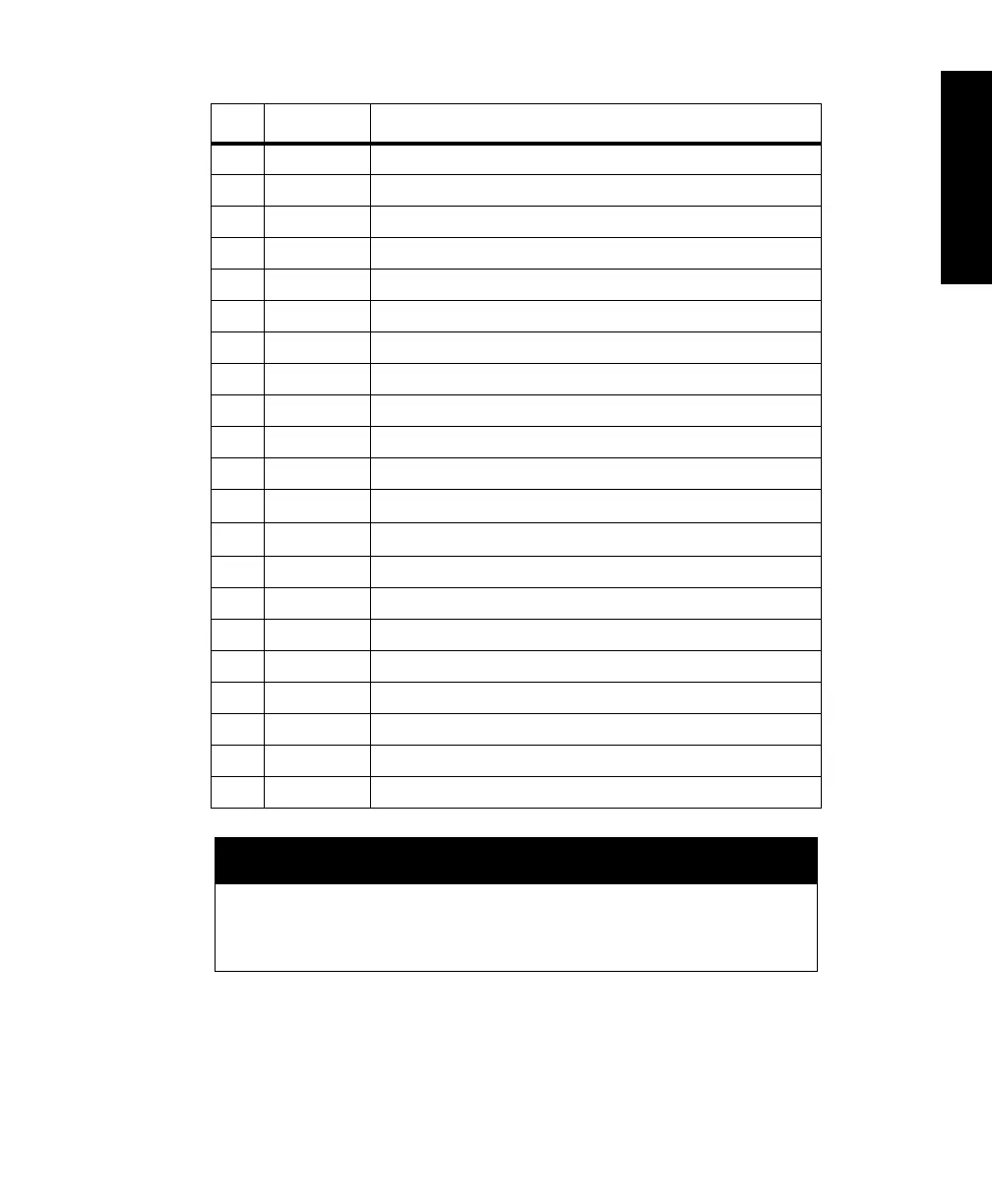
10 RTSB RS-232 Port B request to send
11 RXDB RS-232 Port B receive data
12 FSX Ashtech internal use only (leave floating)
13 +5V +5 VDC input
14 +5V +5 VDC input
15 BATT_IN 2.5-3.5 volt battery backup for memory and real-time clock
16 CLKRX Ashtech internal use only (leave floating)
17 MAN_RES* Connect to ground for manual hardware reset
18 1PPS_OUT 1 pps TTL output synchronized to GPS time
19 GND G12 chassis common ground
20 GND G12 chassis common ground
21 LED_RED
External LED control output (3.3 Volts through 100
W)
22 LED_GRN
External LED control output (3.3 Volts through 100
W)
23 MSTR_OUT Measurement strobe output
24 GND G12 chassis common ground
25 VARF_OUT Variable frequency output
26 GND G12 chassis common ground
27 PHOTO_IN Photogrammetry pulse input
28 FSR Ashtech internal use only (leave floating)
29 SERBLEN* Ashtech internal use only (leave floating)
30 DR Ashtech internal use only (leave floating)
CAUTION
• If pin 15 (BATT_IN) is not used, it should be connected to ground (GND)
• If pin 17 (MAN_RES*) is not used, it should be left open
• If pin 17 (MAN_RES*) is used, it can be pulled to ground (GND) using a
switch, or driven to ground with an open-collector gate.
Table 1.2. J301 Pin Assignments (Continued)
Pin Code Description
G12RevD.book Page 7 Tuesday, April 2, 2002 4:33 PM