6 G12 OEM Board & Sensor Reference Manual
LED, a connection for battery-backup for RAM maintenance, an input for manual
hardware reset, an output for a TTL-level timing pulse, a photogrammetry time-
tag input, and a measurement strobe output. Figure 1.2 lists the pin assignments
for J301.
CAUTION
To avoid damage to the G12 OEM board, ensure that pin 1 of the con-
necting cable is attached to pin 1 on J301 as indicated in the drawing.
In addition, the power source should be turned off while connecting
or disconnecting cables to or from the J301 connector.
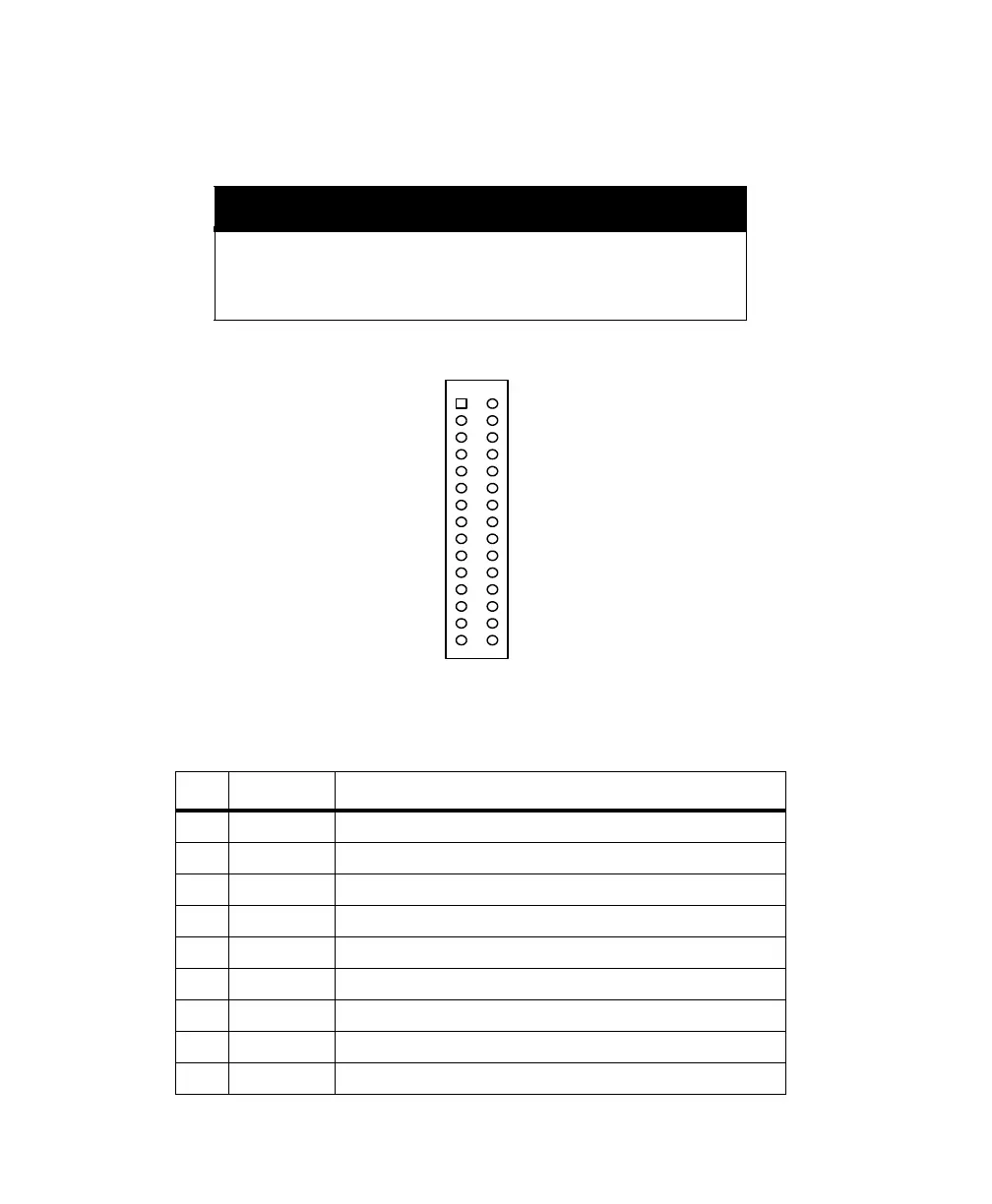
Figure 1.2. J301 Pin Assignments
Table 1.2. J301 Pin Assignments
Pin Code Description
01 GND Ground for serial Port A
02 CTSA RS-232 Port A clear to send
03 TXDA RS-232 Port A transmit data
04 RTSA RS-232 Port A request to send
05 RXDA RS-232 Port A receive data
06 DX Ashtech internal use only (leave floating)
07 GND Ground for serial Port B
08 CTSB RS-232 Port B clear to send
09 TXDB RS-232 Port B transmit data
GND
TXDA
RXDA
GND
TXDB
RXDB
+5V
BATT_IN
MAN_RES
GND
LED_RED
MSTR_OUT
VARF_OUT
PHOTO_IN
RESERVED FOR INTERNAL USE
CTSA
RTSA
RESERVED FOR INTERNAL USE
CTSB
RTSB
RESERVED FOR INTERNAL USE
+5V
RESERVED FOR INTERNAL USE
1PPS_OUT
GND
LED_GRN
GND
GND
RESERVED FOR INTERNAL USE
RESERVED FOR INTERNAL USE
J301
1
3
5
7
9
11
13
15
17
19
21
23
25
27
29
2
4
6
8
10
12
14
16
18
20
22
24
26
28
30
G12RevD.book Page 6 Tuesday, April 2, 2002 4:33 PM