20 G12 OEM Board & Sensor Reference Manual
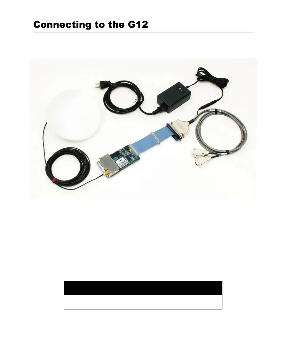
Figure 2.1 shows how to connect the components in the G12 Board system.
Power
Before applying power, connect any controller devices or data logging equipment
to the input/output ports of the G12 by way of connector J301. Applying power to
the power input pins on connector J301 starts G12 operation.
Removing power from the power input pins on connector J301 stops G12
operation.
Figure 2.1. G12 Board Connections
CAUTION
To avoid damage to the G12, always turn off the power supply before
connecting or disconnecting connector J301.
Interface
Cable
G12 Board
Power I/O
Cable
Universal Power
Supply
Antenna
Antenna
Cable
G12RevD.book Page 20 Tuesday, April 2, 2002 4:33 PM