Page 15
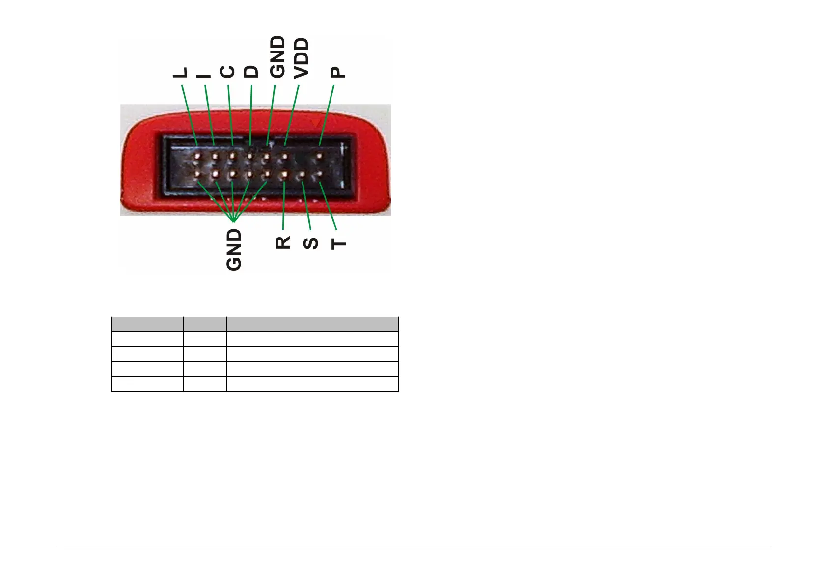
Fig.3: Programming connector
signal input/output or VPP output
Table1: programming connector
2.5.2 GO Button
This button simplifies work with the application being
programmed. It triggers device programming or another
pre-programmed function. For further information on
settings see Setting the GO Button.
2.5.3 LED Indicators
ACTIVE
This two-state LED informs you of the equipment status.
The yellow color means that there is ongoing
communication between the programmer and a device.
A red color signals an error state.
ON-LINE
The green LED informs you that FORTE is connected to a
computer and that the computer and the programmer
“understand each other”, i.e. drivers are installed and
work correctly.
In Linux, the green LED turns on upon connecting the
programmer to a PC even before the driver is correctly
installed.
2.5.4 USB Connector
A standard USB (type B) connector is provided for
connecting to a computer. The programmer uses the
USBHigh-Speed (480 Mbps) interface for communication.
2.6
Connecting to
Application
The programmer should be connected to an application to
be programmed with an ICSPCAB8 or ICSBCAB16 cable.
The cables are designed for 2.54 mm spacing.