Page 86
Notes
• An error may occur if UP cannot program the
calibration word or if a fault occurs during Device ID
reading, UP warns about an overcurrent at VDD, etc.
This may be eliminated by prolonging the charging/
discharging time in the ▸ Delay for VDD switching on/
off when supplied from programmer option - up to
several seconds.
• If UP points out an overcurrent error at VPP, a shorter
ICSP cable may help (its maximum length is 15cm).
5.13.3 ICSP Connector
All ASIX programmers use a unified connector with
2.54mm spacing of pins for programming with the ICSP
algorithm.
This connector has 8pins with 7signals. Not all signals
are always needed for the programming itself.
For further information on connecting a device to the
programmer see Connection Examples.
Table13: ICSP connector
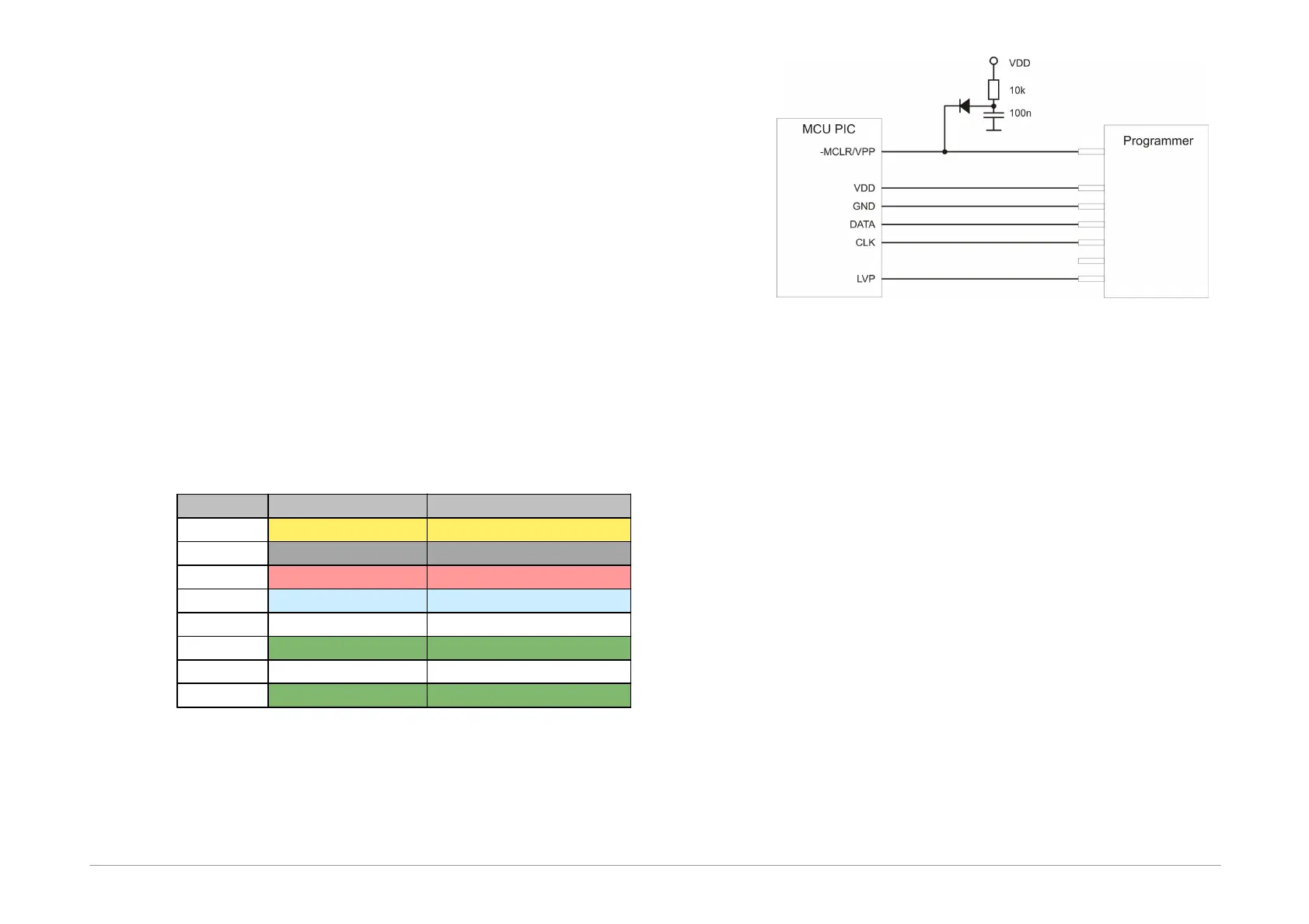
The following drawing illustrates the recommended
connection of -MCLR/VPP pin found in Microchip
microcontrollers for device programming through the
ICSP interface.
Fig.42: Recommended connection of -MCLR/VPP pin
5.14
Appendix C: Intel‑HEX
File Format
This appendix describes the format of Intel-HEX files used
by UP for data reading and saving. .hex is the typical
extension for such a file.
5.14.1 Supported
Alternatives of HEX
Files
UP supports 2 basic alternatives of Intel-HEX files:
• "basic", sometimes also 8-bit Intel-HEX File (e.g.
Microchip MPASMWIN generates this file with
parameter INHX8M).
• "extended", sometimes also 32-bit Intel-HEX File (e.g.
Microchip MPASMWIN generates this file with
parameter INHX32).