Page 17
Please make sure that the GND of the application, the
programmer and the USB are interconnected before
signals and the power are applied.
Important warning
If an application is powered by a switched
power source or is not grounded, a significant
voltage difference may appear between the
programmer’s ground and the application’s
ground. This could damage the programmer.
The simplest way of connecting the GND prior to the
other signals is to ground the application before
connecting it to the programmer. This can, for example,
be achieved by making the GND pin of the application’s
ICSP connector longer than the other pins. It will make
sure that both grounds are interconnected first.
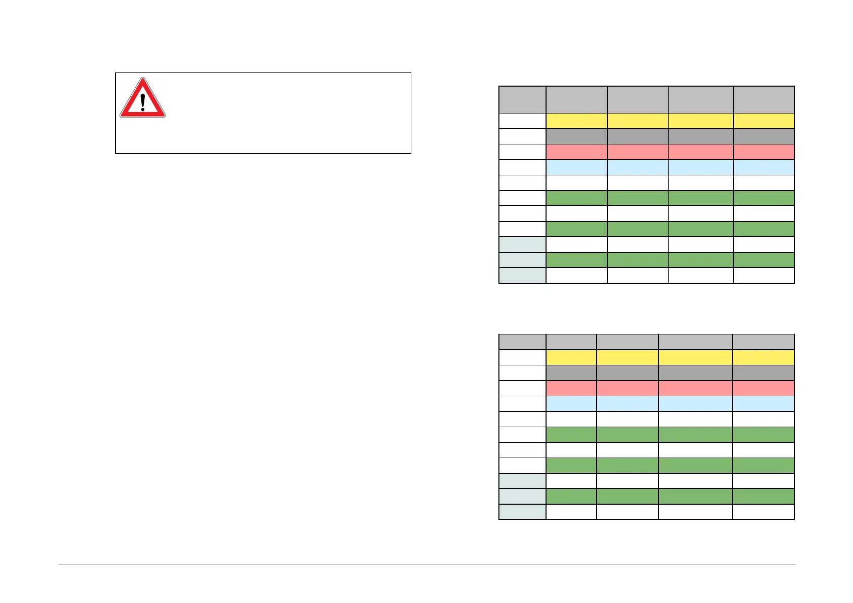
Table of Connections
Table3: Connection list No.1
Table4: Connection list No.2