Page 16
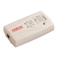
2.6.1 Custom-made
Connecting Cable
Should an application to be programmed have a non-
compatible type of connector for linking to the
programmer, the customer can make his/her own
programming cable. Its length should not exceed 15cm.
This is where interleaving of individual signals with GND
in a 16-wire ribbon cable can be used conveniently. In
order to utilize this ground-interleaving, all GND signals
must be actively connected on the application's side.
The following table lists markings of connectors by FCI
Electronics suitable for making a custom cable. Ofcourse,
it is possible to use any similar ones:
Table2: ICSP cable - material list
A cable with a cross-section between 0.1 and 0.3 mm2
may be used for making the custom connecting cable.
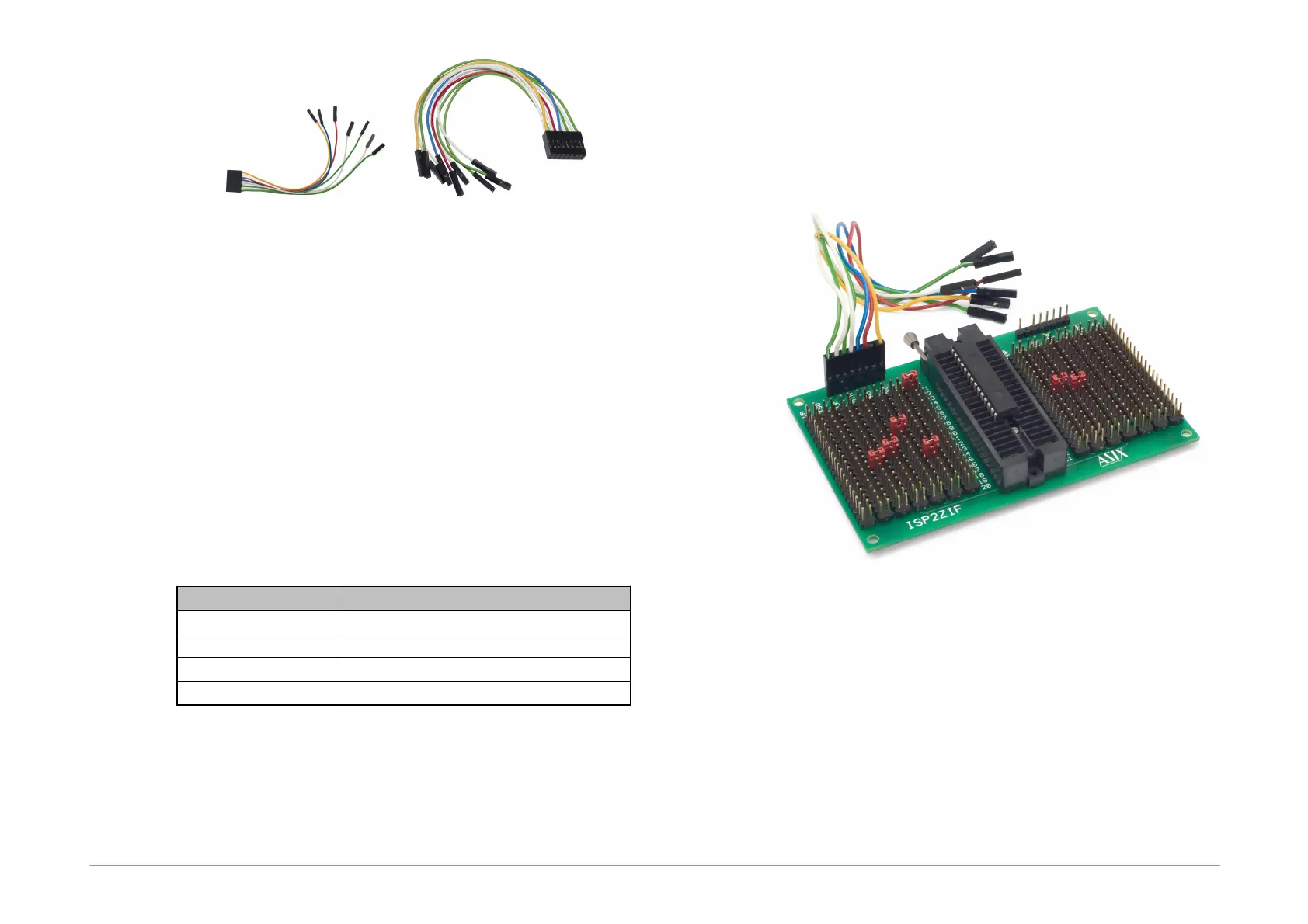
2.6.2 Programming in ZIF
Socket
If programming of autonomous device is required, i.e.
those that are only later connected to an application, it is
possible by means of our optional ISP2ZIF accessory.
ISP2ZIF consists of a zero insertion force (=ZIF) socket
and an ICSP connector for connecting to the programmer,
which can also provide voltage for feeding the program
circuitry.
2.6.3 Connecting
Procedure
The correct procedure for connecting the programmer:
first connect FORTE to the target application, then
connect FORTE to the USB and finally turn on the
application’s power supply.