Page 85
5.13.2 Power Supply
Options
Connecting the shared data and power supply ground
(GND) is obviously necessary for all cases. The
microcontroller being programmed can be fed:
• externally from an application
• internally from a programmer
The external power supply from the application cannot be
used for some types of microcontroller having the -MCLR/
VPP pin alternatively configurable as an I/O.
The internal power supply can be used only in cases
where the application does not draw too much current
from programmer's feeding pin (VDD). The maximum
allowed current consumption can be found in the
Technical Specification.
Both PRESTO and FORTE programmers feature an
overcurrent protection. PRESTO has a software protection
in which an output gets disconnected by the running UP
program having detected an overload. FORTE has a
hardware protection, which does not depend on the
control software.
The programmer switches the power supply off if the
maximum load is substantially exceeded for a certain
time (this time is adjustable). PRESTO checks for the
overload state the whole time the power supply is
connected.
Support for an external power supply is integrated in both
PRESTO and FORTE hardware. The programmer feeds the
input and output circuits with a voltage connected to pin
VDD. The voltage may be lower than 5V.
Advice
When designing the process, please pay special attention
to the type of device to be programmed – if it can be not
only operated but also programmed at a voltage lower
than 5V.
Power Supply Capacities in
Application
If there are capacities present at the application's power-
supply pin that would slow down the power on/off
switching and application is fed from programmer during
programming, longer charging/discharging times need to
be set in UP. In other case UP will probably announce
overcurrent on VDD pin.
An approximate time that should be set in the program:
t[μs] = 2.5 × C[μF] × R[Ω].
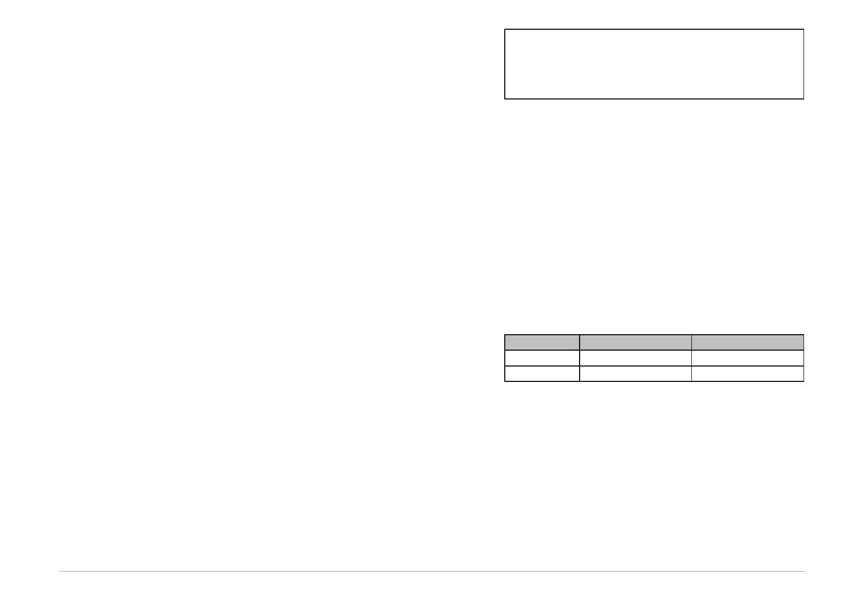
The equivalent resistance is presented in table following
table:
Table12: Equivalent resistance of pin VDD
Example
The necessary charging time for an application with
a33μF capacitor programmed with PRESTO:
2.5×33×50=4125μs
discharging:
2.5×33×1000=82.5ms.
For further information on the setting see ▸ Delay for VDD
switching on/off when supplied from programmer.