CHAPTER 4 REFERENCE GUIDE
Page 4-26
091-00027-001 REV A Evolution Backup Display Pilot’s Guide
Page 4-27
091-00027-001 REV A
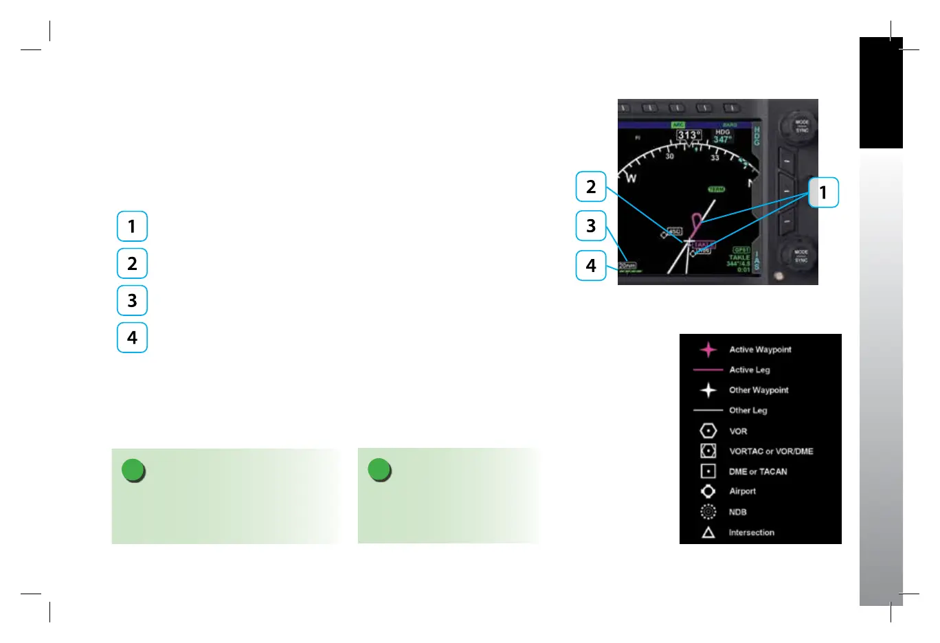
4.4.5. Basemap Overlays
The Basemap comprises symbols depicting the location of ight plan waypoints and
legs, airports, VORs, DMEs, NDBs, and intersections. The Basemap is always oriented
with magnetic heading up and centered so that the current aircraft position coincides
with the aircraft’s Ownship Symbol. The current Basemap declutter level and range are
shown on the lower left side of the display (Figure 4-89).
Basemap Symbols
Aircraft Ownship Symbol
Basemap Range
Basemap Declutter Level
When enabled, the Basemap features on the Navigation Display are displayed and
layered as detailed in Table 5-12. The GPS ight plan is rendered in either straight or
curved lines, as supported by the congured GPS navigator. The displayed symbol set
includes active waypoints, active ight plan leg, ight plan waypoints, ight plan legs,
airports, VORs, VORTACs, TACANs, DMEs, intersections, and NDBs (Figure 4-90).
NOTE
A VORTAC is shown as a combined
VOR and DME symbol. A TACAN is
rendered as a DME symbol.
NOTE
All map and ight plan elements are received
from the GPS and are only available from
compatible GPS navigators (e.g. GNS 430/530).
Figure 4-89
Basemap (ARC CDI Compass Mode Shown)
Figure 4-90
Basemap Symbol Set
091-00027-001 Rev A EBD Pilots Guide V&H .indb 27 8/27/14 8:51 AM