TECHNICIANS' manual 17 of 104
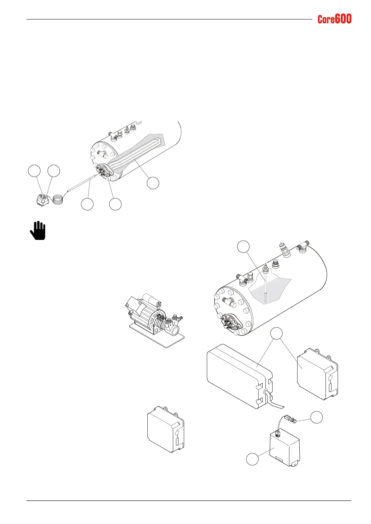
2.10.9 Safety thermostat
The thermostat prevents any damage occurring to the elec-
trical heating element if there is no water in the heating unit.
The thermostat bulb (7) is located inside a sheath (8) in the
middle of the heating elements. The thermostat contacts (9)
are connected to the electric heating element (10). If the
electricheatingelementisexposedduetoafailuretollthe
heating unit with water, the temperature of the heating el-
ement increases dramatically. At this point, the thermostat
cuts the power supply to the heating element in order to pre-
vent damage occurring.
10
911
7
8
To reset the thermostat, press the centre button
(11). However, before starting the machine up
again, identify what prevented the water from be-
ing fed into the heating unit.
2.10.10 Motor pump
This component feeds the machine
by increasing the water pressure to
0.8-0.9 MPa (8-9 bar) in order to dis-
pense coffee and automatically ll
the heating unit.
2.10.11 Electronic control unit
The electronic control unit is installed on the SAE versions.
Its purpose is to electronically control the cof-
fee dose via the water owing through the
dosing device and to check that the heating
unitisbeinglledwithwater.
Some versions of the control unit are set up
to be connected to the dispensing account-
ingsystemsbymeansofaspecicinterface
device.
2.10.12 Automatic Water Entry
The Automatic Water Entry system is designed to check the
water level in the heating unit. It consists of:
• A probe inserted into the heating unit (1) consisting of a
stainless steel rod.
• The standard control unit (2) on SAE versions and the elec-
tronic level regulator on the other versions (3).
• A hydraulic circuit with a solenoid valve controlled by the
regulator.
The electronic control unit controls the level of water in the
heating unit. When the level of water in the heating unit
drops, the contact with the probe is interrupted. The control
unit sends an impulse to the inlet solenoid valve and the mo-
tor pump, which are then activated until the normal level of
water in the heating unit has been restored.
To avoid any ooding caused by machine malfunctions or
water leaks in the circuit, the electronic control unit has a
“Timeout”featurewhichcutsofftheautomaticwaterlling
function after a certain time (2 minutes). The LED (4) located
on the front of the machine body comes on to indicate acti-
vation of this system. When installing machines with three
orfourgroups,theinitial waterlling timemayexceedthe
established timeout limit. Should this occur, simply turn the
machine off and then back on to restore normal operating
conditions.
1
2
4
3



 To Next Page