TECHNICIANS' manual26 of 104
The water mains must supply cold water t for hu-
man consumption (potable water) at a pressure
between 0.15-0.6 Mpa (1.5 and 6 bar). If the pres-
sure is higher than 0.6 MPa (6 bar), connect a pressure re-
ducer before the pump.
All the lling couplings are 3/8 male gas types. The drain
tray is connected to a pipe with an internal diameter of 20
mm.
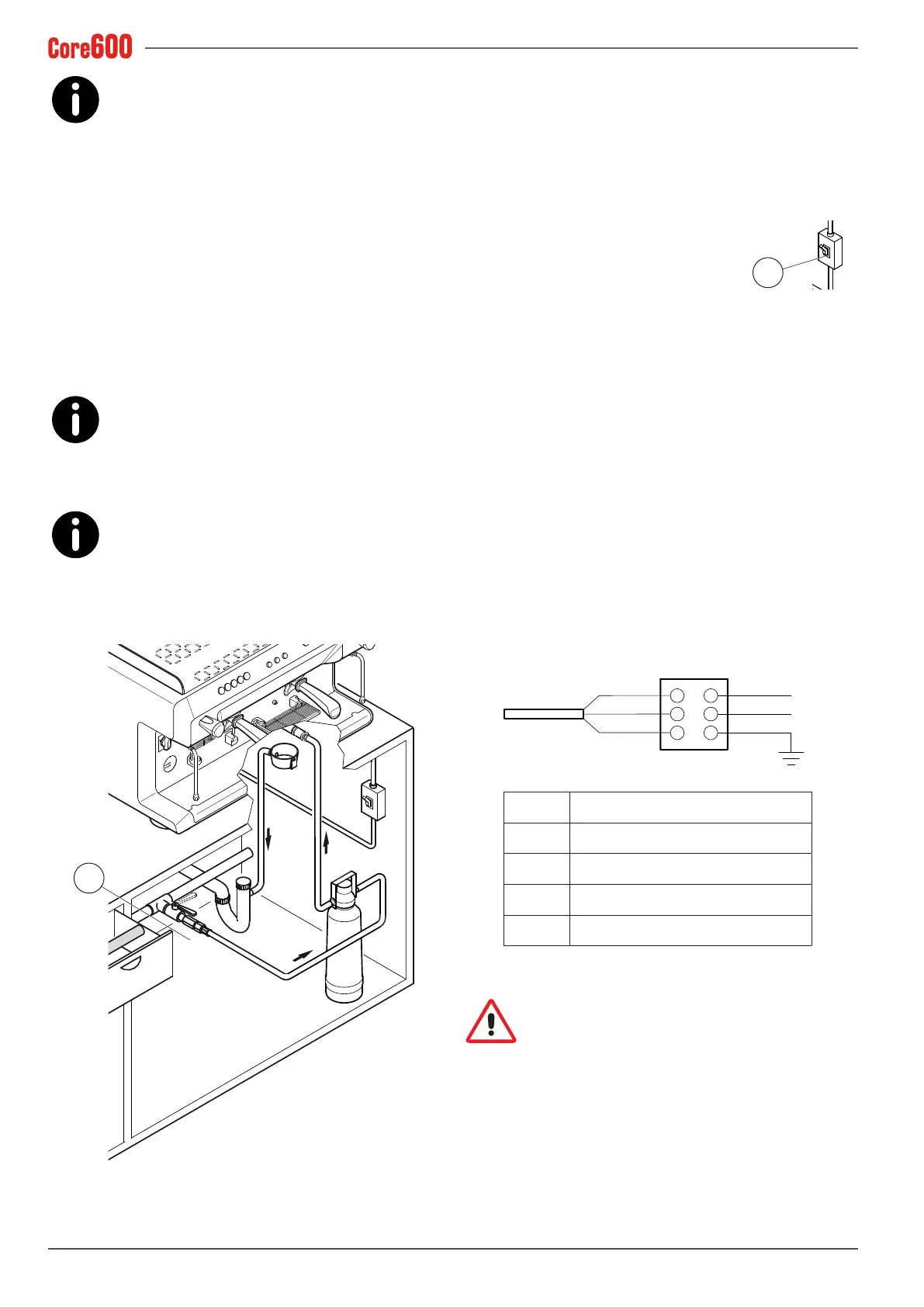
If an external tank is used, the connection pipe between the
machine and the tank must not exceed 150 cm.
The machines are tted with a "Timeout" device which al-
lows the heating unit to be lled up with water within a
maximum time. This function prevents water from owing
out of the heating unit's valve (ooding) and keeps the mo-
tor pump from overheating.
FOR THE EUROPEAN COMMUNITY: when con-
necting to a water mains or an external tank, a
non-return valve (12) must be positioned upstream
from the machine, as set forth by the EN 1717 standard.
FOR THE USA - The water connections and drains
must be made in accordance with the 2003 Inter-
national Plumbing Code of the International Code
Council (ICC), or the 2003 Uniformed Hydraulic Code of the
IAPMO. The machine must be installed with a suitable non-
return valve as set forth by the national standards.
12
5.7.4 Electrical connection
• The conformity of the electrical system, effectiveness of
the earthing system and functionality of the differential
circuit breaker - all of which are fundamental for guaran-
teeing the appliance’s electrical safety - are the responsi-
bility of the person in charge of the electrical system on
which the equipment is installed.
• Before installation, make sure that the
electrical system is equipped with the
protection device (8), as indicated in the
safety notes on page 30.
• To connect the machine to the electric mains, refer to
Chap. "14. WIRING DIAGRAMS" on page 77.
• Do not use extension leads or electrical adapters for mul-
tiple outlets.
• The access spaces to the machine and main switch must
be left clear, in order to allow the user to intervene without
any constrictions and leave the area immediately when
needed.
If an external motor pump is being used, proceed as follows:
• Connect the motor pump cable (with the smaller cross-
section) to the connector of the external motor as shown
in the diagram below.
• Connect the machine power cable (with the larger cross-
section) as indicated in Chap. "14. WIRING DIAGRAMS"
on page 77.
MP
B
B
M
M
C
GV
GV
B Blue
C Motor pump power cable
GV Yellow-green
M Brown
MP Motor pump terminal
Every electrical connection operation must be car-
ried out with the mains off and the power supply
disconnected. The Technician must also check that
there is no voltage present, by using a multimeter, for exam-
ple.
8






 To Next Page