TECHNICIANS' manual 63 of 104
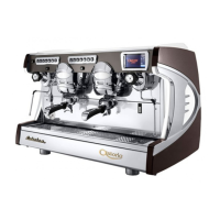
8.3.4 Dispensing group maintenance
Replace the dispensing group's
shower screen (2) and group gas-
ket (4) on a quarterly basis (we rec-
ommend only using original spare
parts), by proceeding as follows:
• Unscrew the screw (1).
• Remove the shower screen con-
tainment ring (3).
• Replace the group shower
screen (2) and the rubber group
gasket (4).
• Reassemble the components.
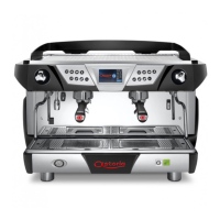
8.3.5 SAFETY VALVE check
The pressure relief valve is one of the main components for
machine safety. Therefore, it is important to carry out the fol-
lowing checks:
First check:
• Remove the machine's upper grille.
• Use pliers to pull the valve pin (6) upwards.
• If the pin will not budge, it probably means that the valve
is encrusted with limestone and must be replaced.
Second check:
• Turn the machine off.
• Close off the pressure switch contacts.
• Turn the machine back on and wait for the
pressure in the heating unit to rise.
• Check that the valve is working correctly at
the maximum pressure of 0.19 bar (1.9 bar).
If any malfunctions are detected, the
valve must be replaced. Only use the Manufactur-
er's original Safety Valves.
1
2
3
4
6
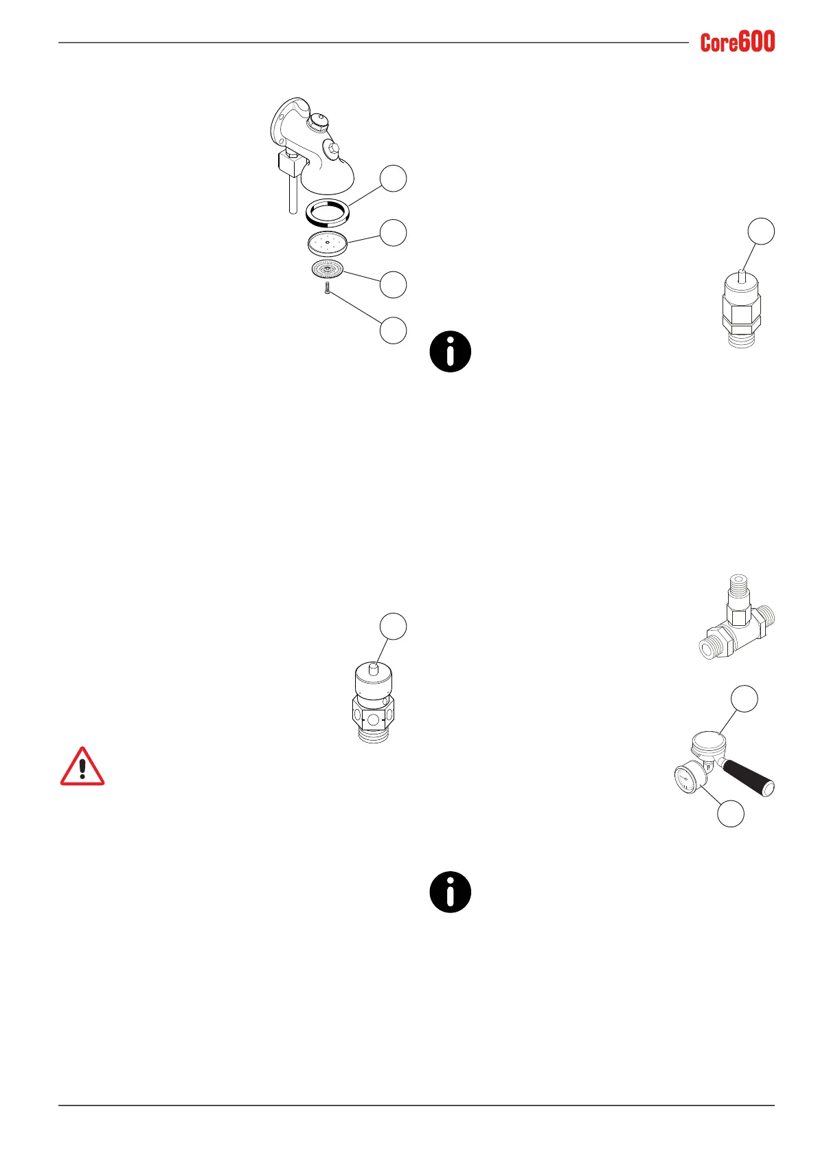
8.3.6 NEGATIVE PRESSURE VALVE check
First check:
• Remove the machine's upper grille.
• Use pliers to push the valve pin (5) downwards.
• If the pin will not budge, it probably means that the valve
is encrusted with limestone and must be replaced.
Second check:
• Turn the machine off.
• Open the steam valves and release all the pres-
sure from inside the heating unit.
• Turn the machine back on and check that the
valve is closing normally.
If any malfunctions are detected, the
valve must be replaced.
8.3.7 NON-RETURN DRAIN VALVE check
The non-return drain valve is an important component for
the correct operation of the machine. Perform the check as
follows:
• Activate the dispensing groups for about 30 seconds.
• Attach a lter holder (7) with a pressure
gauge (available on request) to the dis-
pensing group.
• Activate the dispensing group, and use the
pressure gauge (8) to monitor the pressure
as it increases up to 0.8-0.9 MPa (8-9 bar).
• Check that the pressure is increasing
due to the heated water expanding
until it reaches approximately 1.2 MPa
(12 bar): when this value is reached,
it conrms that the valve is working
correctly and the seals and solenoid
valves are tight.
• Stop dispensing.
• Repeat the check on the other dispens-
ing groups.
If any malfunctions are detected, the valve must
be replaced.
5
7
8