Manual, F/T Sensor, Data Acquisition (DAQ) Systems
Document #9620-05-DAQ.indd-20
Pinnacle Park • 1031 Goodworth Drive • Apex, NC 27539 • Tel: 919.772.0115 • Fax: 919.772.8259 • www.ati-ia.com • Email: info@ati-ia.com
42
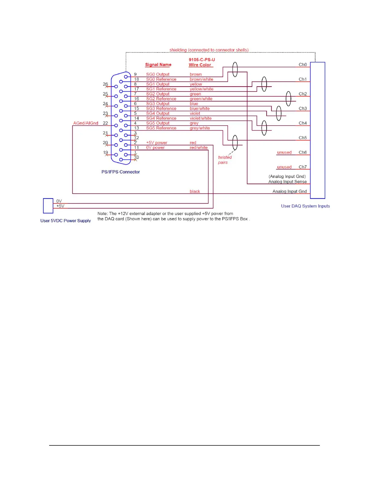
Figure 4.15—Single-Ended Connections to a Data Acquisition System
A connection from the DAQ F/T’s AGnd/AIGnd line to the data acquisition system’s
analog input ground or analog ground is required in most cases. This line allows the
return of the small amount of current used by the data acquisition system. Noise can
result if this current isn’t returned via the AGnd/AIGnd path.
For best noise performance, the cabling from the PS/IFPS connector should be
shielded and each strain gage’s signals in a twisted pair. The shielding should be
connected to the PS/IFPS connector shell and to the shell of the data acquisition
system’s connector. If the data acquisition system has no connector or its connector
shell is electrically oating, then the shield at the PS/IPFS connector should be
connected to the AGnd/AIGnd signal.
It may be important to consider the voltage drop of the +5V and 0V power lines to
certify a sufcient voltage is delivered to the PS/IFPS box. Note: that as the delivered
voltage drops, the current consumption will increase.
 Loading...
