Manual, F/T Sensor, Data Acquisition (DAQ) Systems
Document #9620-05-DAQ.indd-20
Pinnacle Park • 1031 Goodworth Drive • Apex, NC 27539 • Tel: 919.772.0115 • Fax: 919.772.8259 • www.ati-ia.com • Email: info@ati-ia.com
59
6.3.1 Removing and Replacing the IFPS Card for Recalibration
Tools required: #2 Phillips head screw driver
Parts required: 9105-IFPSMC-PCB
NOTICE: The following steps need to be done at an anti-static workstation.
NOTICE: Make sure the transducers are re-connected to the same connector on the
front panel when re-assembling the IFPSMC box. Also ensure the transducers and the
connector on the front panel are clearly marked with the serial number label.
1. Disconnect all cables, transducers and the power supply from the IFPSMC box.
2. Remove the (4) M4 pan head screws from the front panel using a phillips head screw driver.
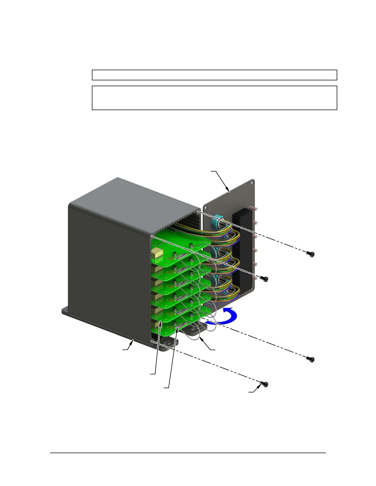
3. Carefully rotate the front panel open to the right side of the box, as shown in Figure 6.1.
Figure 6.1—IFPSMC Box Disassembly
(4) M4 Pan Head Screw
Front End Plate with
Transducer Connectors
IFPSMC Box
IDAQ PS Board Assembly
Plastic Loops
FT Serial Number Label
4. Identify the IFPS card to be removed by following the wires from the associated transducer
connector.
5. Disconnect the IFPS card from the backplane by rmly holding the top of the IFPSMC box and
simultaneously pulling the two plastic loops attached to each board. Slide the board out.
 Loading...
