Manual, F/T Sensor, Data Acquisition (DAQ) Systems
Document #9620-05-DAQ.indd-20
Pinnacle Park • 1031 Goodworth Drive • Apex, NC 27539 • Tel: 919.772.0115 • Fax: 919.772.8259 • www.ati-ia.com • Email: info@ati-ia.com
43
4.5.5.3 Using Unused DAQ Card Resources
Additional functions not used in the standard conguration are available on the ATI-
supplied DAQ card; however, information on using these resources is outside the
scope of this manual. Users who wish to use the ATI-supplied DAQ card will need
to consult the DAQ card documentation for connections and functionality. Table 4.11
and Table 4.12 show which signals are used by the F/T system and cannot be used for
other purposes. If designed improperly, additional connections to the DAQ card may
introduce ground loops and noise.
Table 4.9—9105-IFPSMC Scan List for Each Transducer
Transducer National Instruments Scan List
1 devx/ai4:7, devx/ai16:17
2 devx/ai18:23
3 devx/ai32:37
4 devx/ai38:39, devx/ai48:51
5 devx/ai52:55, devx/ai64:65
6 devx/ai66:71
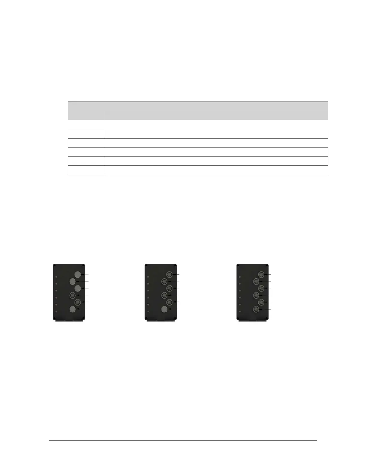
4.5.6 Transducer Connections on a Multi-Sensor IFPSMC Box
The IFPSMC transducer connectors are numbered 1 through 6, with the rst transducer located at
the bottom of the box. Current IFPSMC models have all transducer connectors populated in the
front plate; depending on the model, however, certain models may not have the associated IFPS
cards installed. Previous versions were not supplied with all transducer connectors or associated
IFPS cards installed, refer to Figure 4.16.
Figure 4.16—IFPSMC Box Transducer Connections
Current Version
Multi-sensor Interface Box
Transducer Connector 1
Transducer Connector 2
Transducer Connector 3
Transducer Connector 4
Transducer Connector 5
Transducer Connector 6
Transducer Connector 6
Transducer Connector 5
Transducer Connector 4
Transducer Connector 3
Transducer Connector 2
Connector 1 Plugged
Connector 1 Plugged
Transducer Connector 2
Transducer Connector 3
Connector 4 Plugged
Connector 5 Plugged
Connector 6 Plugged
(9105-IFPSMC-5 Shown)
Previous Version
Multi-sensor Interface Box
(9105-IFPSMC-2 Shown)
Previous Version
Multi-sensor Interface Box
Table 4.10 shows the channel assignments for the 9105-IPFSMC and National Instruments card,
using National Instruments’ nomenclature. Note: that with the IFPSMC, transducers are generally
assigned such that unused channels are grouped together. Channels that do not have a transducer
assigned to them by ATI may be used for other purposes through the (connector 0 from user) and
(connector 1 from user) connectors, only if the 12 pin jumpers are installed on the backplane inside
the IFPSMC box. Refer to Section 4.5.6.1—Installing 12 Pin Jumpers on the Backplane to Make
Unused Transducer Signals Available to the User
DAQ card signals unused by the IFPSMC electronics are made available to the user via the
connectors labeled (connector 0 from user) and (connector 1 from user). The signal names and pin
assignments of these connectors match those of connectors connector 0 to DAQ card and connector
1 to DAQ Card, respectively. DAQ card signals used by the IFPSMC electronics are not connected
on either user connector. For signal names and pin assignments of DAQ card connectors 0 and 1,
refer to the NI DAQ card pinout section of National Instruments M-Series documentation or Table
4.11 and Table 4.12.
 Loading...
