Manual, F/T Sensor, Data Acquisition (DAQ) Systems
Document #9620-05-DAQ.indd-20
Pinnacle Park • 1031 Goodworth Drive • Apex, NC 27539 • Tel: 919.772.0115 • Fax: 919.772.8259 • www.ati-ia.com • Email: info@ati-ia.com
18
3. System Functionality
This section provides a functional outline of the F/T system. The F/T system is broken into four areas:
Mechanical, Electrical, Load Calculations, and ATI DAQ Software.
3.1 Mechanical Description
The transducer responds to applied forces and torque in accordance with Newton’s third law which states:
For every action there is always an opposed or equal reaction; or, the mutual action of two bodies upon each
other are always equal, and directed to contrary parts.
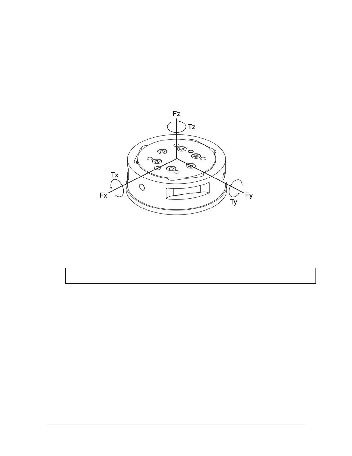
Figure 3.1—Applied Force and Torque Vector on Transducer
The force applied to the transducer exes three symmetrically placed beams using Hooke’s law:
s = E·e
s = Stress applied to the beam (s is proportional to force)
E = Elasticity modulus of the beam
e = Strain applied to the beam
NOTICE: The transducer is a monolithic structure. The beams are machined from a solid piece
of metal. This decreases hysteresis and increases the strength and repeatability of the structure.
Semiconductor strain gages are attached to the beams and act as strain-sensitive resistors. The resistance of
the strain gage changes as a function of the applied strain as follows:
∆R = S
a
·R
o
·e
∆R = Change in resistance of strain gage
S
a
= Gage factor of strain gage
R
o
= Resistance of strain gage unstrained
e = Strain applied to strain gage
 Loading...
