Manual, F/T Sensor, Data Acquisition (DAQ) Systems
Document #9620-05-DAQ.indd-20
Pinnacle Park • 1031 Goodworth Drive • Apex, NC 27539 • Tel: 919.772.0115 • Fax: 919.772.8259 • www.ati-ia.com • Email: info@ati-ia.com
39
4.5.4 PS and IFPS Signals
4.5.4.1 PS 20-pin Circular Connector
The PS 20-pin circular connector signals and pin numbering are the same as the 9105-
TIF transducer signals listed in Section 4.5.3—Transducer Signals. See Table 4.6.
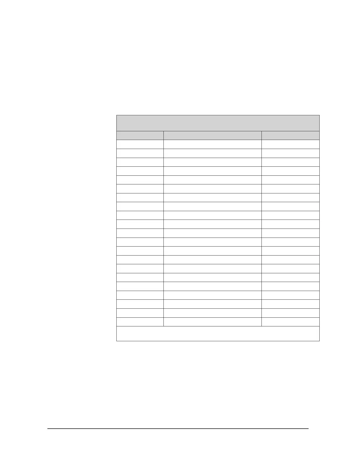
4.5.4.2 PS and IFPS 26-pin High Density D-Subminiature Connector
This connector mates to an industry standard female 26-pin high-density
D-subminiature connector with screw locks. Refer to Table 4.7 for wire colors use with
9105-C-PS-U cable assemblies.
Table 4.7—PS box and IFPS box connector connections and
9105-C-PS-U cable wire colors
Pin Number Description Wire Colors
1 Reserved Orange
2 +5V power input Red
3 T out White
4 SG5 output Grey
5 SG4 output Violet
6 SG3 output Blue
7 SG2 output Green
8 SG1 output Yellow
9 SG0 output Brown
10 Reserved Orange/White
11 0V power input Red/White
12 T ref White/Black
13 SG5 reference Grey/White
14 SG4 reference Violet/White
15 SG3 reference Blue/White
16 SG2 reference Green/White
17 SG1 reference Yellow/White
18 SG0 reference Brown/White
19 Reserved Black/White
22 AIGnd Black
Shell Shielding Shield
Note: The AIGnd is an Analog Input Ground used for input current return from data
acquisition card. The black wire is from the Black / Black/White pair.
 Loading...
