Manual, F/T Sensor, Data Acquisition (DAQ) Systems
Document #9620-05-DAQ.indd-20
Pinnacle Park • 1031 Goodworth Drive • Apex, NC 27539 • Tel: 919.772.0115 • Fax: 919.772.8259 • www.ati-ia.com • Email: info@ati-ia.com
38
4.5.3 Transducer Signals
Details on the connections for transducers with on-board electronics (9105-TIF part numbers).
These transducers have a 20-pin connector. User connections to transducers without on-board
electronics (9105-TWx part numbers) are not supported and therefore not covered in this document.
A 9105-TIF transducer connector mates to a Hirose HR25-9TP-20S connector. A 9105-TIF-x-IPx
Transducer connector mates to a Lemo FGG.3K.320 connector. Refer to Table 4.6 for wire colors
use with 9105-C-x-U cable assemblies.
NOTICE: Multi-colored wires are identied as follows: The rst color listed is the
predominant color of the wire and the second color is the stripe on the wire.
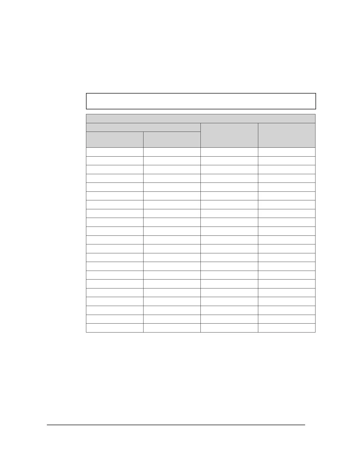
Table 4.6—Transducer connector connections and 9105-C-x-U cable wire colors
Pin Number
Description Wire Colors
9105-TIF
Transducer
9105-TIF-x-IPx
Transducer
1 7 SG0 output Brown
2 5 Reserved Orange
3 8 SG0 reference Brown/White
4 14 SG3 reference Blue/White
5 18 SG5 reference Grey/White
6 1 +VANA power input Red
7 9 SG1 output Yellow
8 13 SG3 output Blue
9 17 SG5 output Grey
10 4 AGnd power input Black
11 2 -VANA power input Red/White
12 10 SG1 reference Yellow/White
13 15 SG4 output Violet
14 19 T out White
15 3 Reserved Black/White
16 6 Reserved Orange/White
17 11 SG2 output Green
18 16 SG4 reference Violet/White
19 20 T ref White/Black
20 12 SG2 reference Green/White
Shell Shell Shielding Shield
 Loading...
