Manual, F/T Sensor, Data Acquisition (DAQ) Systems
Document #9620-05-DAQ.indd-20
Pinnacle Park • 1031 Goodworth Drive • Apex, NC 27539 • Tel: 919.772.0115 • Fax: 919.772.8259 • www.ati-ia.com • Email: info@ati-ia.com
20
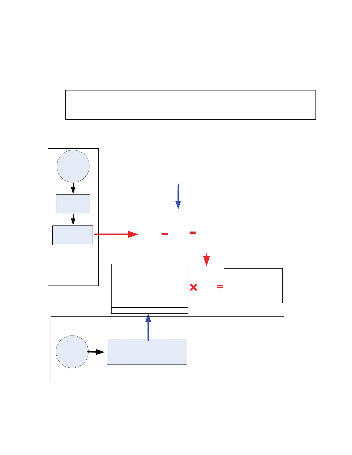
3.3 Load Calculation
Calculations must be performed to derive the loads sensed at the transducer. The transducer reports the
loads as composite values that require conversion to values corresponding to the six Cartesian axes. ATI
supplies software to perform these calculations. Both the software and the transducer’s calibration values
can be accessed from the media that accompanies the transducer. Figure 3.4 shows the calculation required
to convert strain gage data into force and torque data. This method can be used in Matlab, or through other
software that enables manual matrix calculations.
NOTICE: The CD included with the DAQ system contains extensive help les on its software
that will benet both the beginner and advanced user. The CD even includes a spreadsheet to
help advanced users with calculations, see the Advanced Techniques section of the help le for
more information.
Figure 3.4—FT Matrix Calculations
STG0
STG1
STG2
STG3
STG4
STG5
bias0
bias1
bias2
bias3
bias4
bias5
bSTG0
bSTG1
bSTG2
bSTG3
bSTG4
bSTG5
FyG0
FzG0
TxG0
TyG0
TzG0
FyG1
FzG1
TxG1
TzG1
TzG1
FyG2
FzG2
TxG2
TyG2
TzG2
FyG3
FzG3
TxG3
TyG3
TzG3
FyG4
FzG4
TxG4
TyG4
TzG4
FyG5
FzG5
TxG5
TyG5
TzG5
Runtime Matrix
Bias Vector for
Offset Correction
Operations marked RED are to be performed
for each measurement sample.
Operations marked BLUE are to be performed
only once at the beginning of a measurement.
Transducer
ATI Amplifier
(if included)
Customer’s
Data Acquisition
System
6 gage output
voltages data
Transducer
Calibration
File
Open Excel sheet on the website at
http://www.ati-ia.com/Products/ft/
software/daq_software.aspx, called
“DAQ F/T Manual Calculations”
Working
calibration matrix
Determine Offset
Correction Voltage
bias0
bias1
bias2
bias3
bias4
bias5
Note:Temperature compensation
is usually not required. Only older
models may need software
temperature compensation.
Calibration Matrix
Strain
Gage
Data
Force and
Torque Data
(Fx Fy Fz Tx Ty Tz)
bSTG0
bSTG1
bSTG2
bSTG3
bSTG4
bSTG5
Load in the FTxxxxx.cal file and copy the working matrix
from the spreadsheet to the blue square area.
3.3.1 Strain Gage Data
Strain gage data represents amplied voltages from the transducers that are converted to digital
data by the Data Acquisition system. Use the demo program to monitor the strain gage data during
installation, this can be use to avoid saturation errors which can damage the transducer.
 Loading...
