Manual, F/T Sensor, Data Acquisition (DAQ) Systems
Document #9620-05-DAQ.indd-20
Pinnacle Park • 1031 Goodworth Drive • Apex, NC 27539 • Tel: 919.772.0115 • Fax: 919.772.8259 • www.ati-ia.com • Email: info@ati-ia.com
60
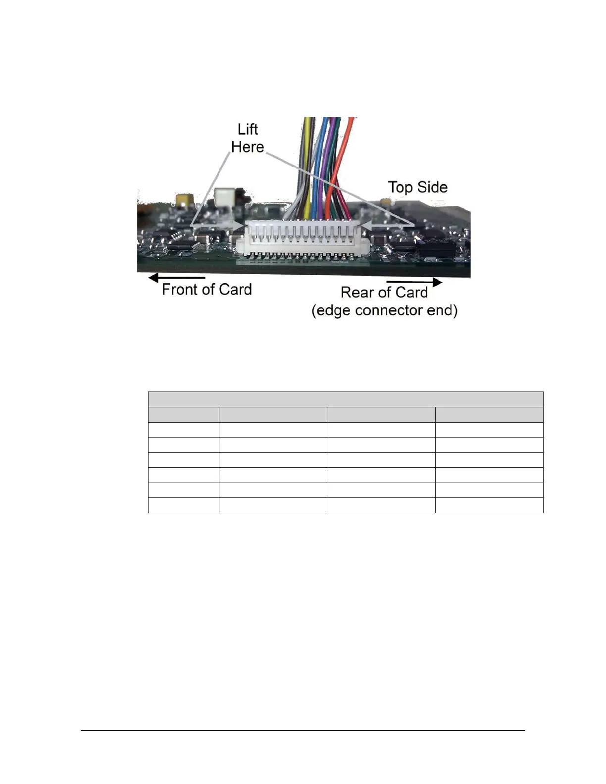
6. Carefully remove the transducer connector harness from the IFPS card by simultaneously
prying up both ends of the connector using your ngernails. See the “Lift Here” call out in
Figure 6.2.
Figure 6.2—Transducer Connector Harness Connection
7. Place the IFPS card into an anti-static bag and send with the transducer to be recalibrated to
ATI.
8. Remove the recalibrated IFPS card from the anti-static bag and note the serial number on the
IFPS card, which slot number it will be installed in, and the serial number of the transducer it
will be connected too. Record this information in Table 6.1 for you to records.
Table 6.1—IFPSMC IFPS Cards and Transducers
Slot IFPS Card SN Transducer FT SN Notes
Transducer 6
Transducer 5
Transducer 4
Transducer 3
Transducer 2
Transducer 1
9. Connect the transducer connector harness from the connector on the front panel to the IFPS
card, as shown in Figure 6.2.
10. Install the IFPS card into the slot in the IFPSMC box. Seat the new IFPS card into the
backplane by pushing the board in until it seats into the backplane connector.
11. Carefully rotate the front panel back into place on the IFPSMC box. Note: be sure not to pinch
any wire between the front panel and the box. Secure the front panel using the (4) M4 pan head
screws,
 Loading...
