S50
13
14
10A
F10
S2a
K5
K4
K4
P0
A1
A2
P7
X11
20 21
X11
10
S20
P1 P2
K100
K100
14
11
14
X11
to Circ.Diagr POWER
Fuses F1-F2, Current Transfo.
B1 B2
X11
8
11
12
33
34
13
14
23
24
13
14
S51
2
2
3
3
X10 13
13
10
10
6
6
11
11
12
12
9
9
X105
5
1
1
14
14
1
2
Y10
11
14
P7
P
S9
M
M6
P7.1
E1
K0
K0
M
M1
G1
-
+
CubicleCanopy
(04)
(06)
X10
B7
S20 - Configuration
ON
P1 P0 P2
OFF
REMOTE
G2
B+
GG
L
GND
C
G
K114
K115
H1
Cubicle
Canopy
31
34
K115
41
44
1514
X11
16
X11
17
S2b
21
22
K1
11
14
K114
S2a
11
12
CC
AA
1514
X11
X19
(08) - Optional
D1
D4
K114
D3
6
X11
13
X11
12
(04)
(04)
a3
4
a3
15
a3
5
a3
55
a6
12
a2
19
a0
125
a0
126
c8
141
a3
142
a3
5
a3
15
a3
4
a3
26
a2
19
a2
13
b2
13
a2
19
a2
19
a3
56
a3
53
b3
10
a3
6
a3
11
a3
28
a3
20
a3
29
a3
65
a3
65
a6
12
a6
12
a6
12
a6
12
a6
12
a6
12
a6
12
a6
12
a6
12
a2
19
a2
19
a2
19
a2
19
a3
30
a3
31
c2
13
a3
35
a3
30
a3
64
a3
51
a3
52
a2
19
a3
14
a3
25
c2
1
c3
3
c3
16
c2
1
c2
1
c2
1
c2
1
c3
3
c3
16
a3
25
c6
12
b6
10
a3
6
a3
11
a6
12
a6
12
i6
12
i6
12
a6
12
a3
25
a3
35
i6
12
i2
2
X11
a3
53
7
X11
a6
12
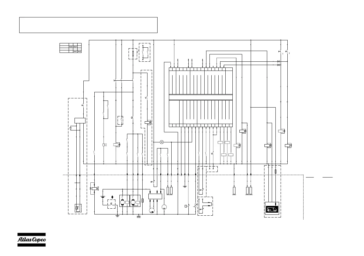
12V
S25
P1
14
13
Lc1003 MKII
Input
15
A1 2221
14201918
0 Vdc (Batt-)
12
51617
ECU Alarm
Generator Voltage L1
Generator Voltage L2
12/24 Vdc (Batt+)
Common for Analogue inputs
Input
W/L-Input D+
Fuel Level (VDO)
Input
Input
CAN-H
CAN-L
GND
Engine CAN-bus Interface
23 24
Generator Voltage L3
Generator Voltage Neutral
25
Generator Current Transfo L1
26
Generator Current Transfo L2
27
Generator Current Transfo L3
29
Generator Current common COM
Low Oil Pressure
333230 31
Emergency StopInput
Remote StartInput
Override fuel shutdown
Input Mains mode
Input
43
Fuel Control Relay
Start Relay Output
Output
Output
10 11 12 13
Output
Output
Output
Output
34
Input
35
Input
Choke
Preheat
Mast up
Mast down
Mast lower position
Mast upper position
Light 1 control
Light 2 control
Light 3 control
Light 4 control
9876
Output
Output
Output
Output
K101
a3
21
K102
a6
12
a3
22
K103
a6
12
a3
23
K104
a6
12
a3
24
W10
X16
8
8
7
7
52
X17
51
a3
51
a3
52
a3
26
a3
27
86
85
A1
A2
A1
A2
A1
A2
A1
A2
30
87
K1
30
87
K5
86
85
A1
A2
a2
19
U2
FM01
+
-
IN_5
X10
14
X11
40 41
11
14
a2
19
a3
15
a3
15
ECU-21
ECU-22
a3
77
ECU-13
a3
15
a3
5
F20
2A
A1
A2
A1
A2
S10
15
16
a2
17
K120
a6
12
A1
A2
K120
14
11
a6
12
a3
68
MSA connector
see ECU diagram
(11)
7
7
15
15
a3
78
a3
77
a2
19
a3
57
S10
14
13
K120
24
21
11.1
11.2
a2
19
H16
(03)
C10
21
24
K4
a3
75
ECU-44
a3
75
4
4
see ECU diagram
X11
X11
X11
11.1
11.2
a2
17
a2
19
b6
12
c3
91
c3
92
c2
2
56
3
1
2
4
c2
13
(03)
b2
5
b2
6
P1
13
14
S11
a3
70
K10
K10
P
M10
i6
12
16
16
X10
b3
37
i2
2
b6
12
11
14
K116
b3
37
11
14
K115
b3
36
X10
ECU-9
see ECU diagram
8
8
a6
12
a6
12
S1
A2
(05)
a2
19
i2
2
bx = 1.5mm² NSGAFOeU
l = 95 mm²
lx = 95 mm² EPR-CSP (BS6195-4C)
k = 70 mm²
j = 50 mm²
i = 35 mm²
54= green/yellow
1 = brown
Wire size Colour code
a = 1 mm²
b = 1.5mm²
c = 2.5mm²
d = 4 mm²
e = 6 mm²
f = 10 mm²
g = 16 mm²
h = 25 mm²
0 = black
2 = red
3 = orange
4 = yellow
5 = green
6 = blue
7 = purple
8 = grey
9 = white
 Loading...