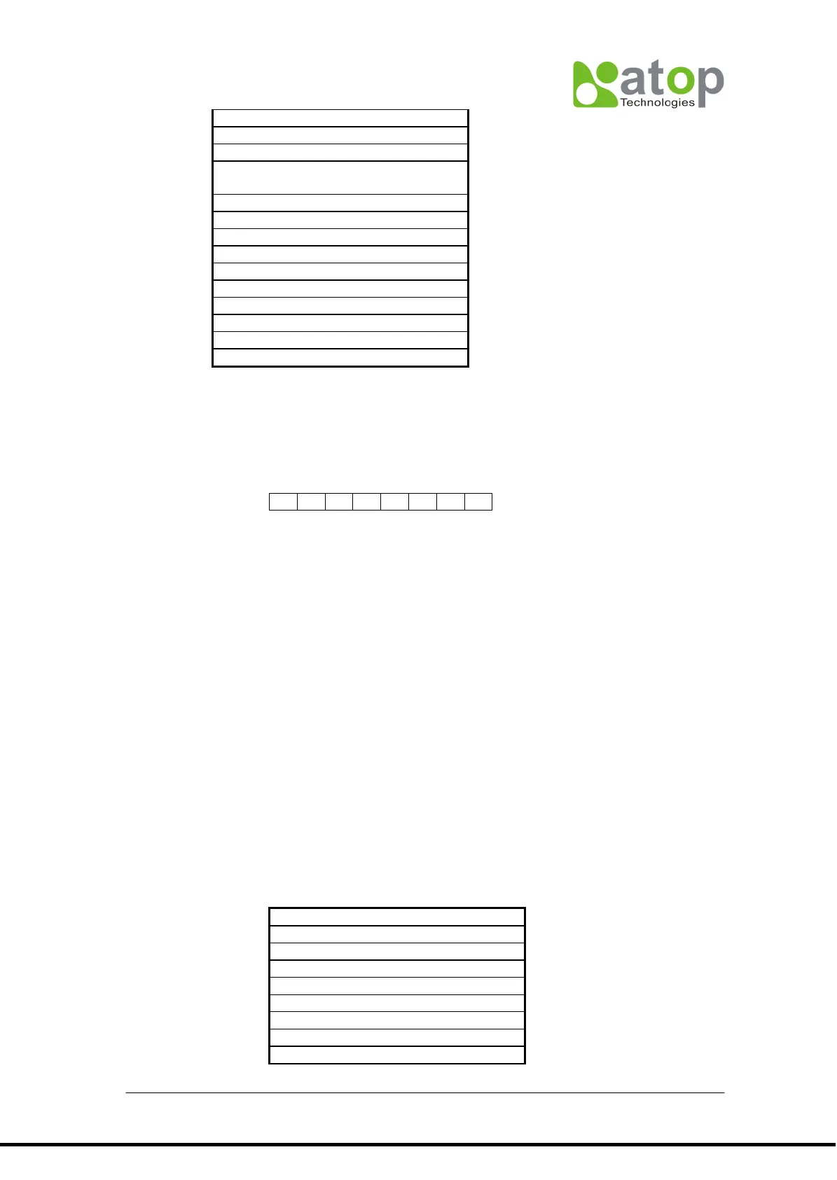
Data[0]: Bit assignment as below
Bit 0~2: 12 digits LED display control
Bit 3 : 0
Bit 4 : Confirmation key control (enable/disable)
Bit 5,6,7: 0
Bit
0 0 0-------12 digits LED display OFF
0 0 1-------12 digits LED display ON
0 1 0-------12 digits LED display, 2 second
blinking
0 1 1--------12 digits LED display, 1 second
blinking
1 0 0--------12 digits LED display, 0.5 second
blinking
1 0 1 ------- 12 digits LED display, 0.25
second blinking
0-----------------------------Disable confirmation key
1-----------------------------Enable confirmation key
Data[1]….Data[12]: message display
Totally 13 data bytes in each buffer, its display format is controlled by 1
st
byte Data(0).
AT50C/AT70C have max. 6 buffers for application.. Data stored in stack buffer according
to receiving order. Each buffer has its own display format respectively.. By scroll-up and
scroll-down key, buffer data can be scrolled up and scrolled down. Pressing “confirmation
key”, displayed data will be uploaded with sub-command 06H if bit4 of data(0) is enabled.
In case disabled, no message sent back.
EX: To show Test-1234567 on LED display, located in address 5, port1 and indicator with
1 second blinking , contents of CCB should be :