Copyright © 2007, 2008 AudioNote Kits
www.AudioNoteKits.com
audionotekits@rogers.com
Page 38
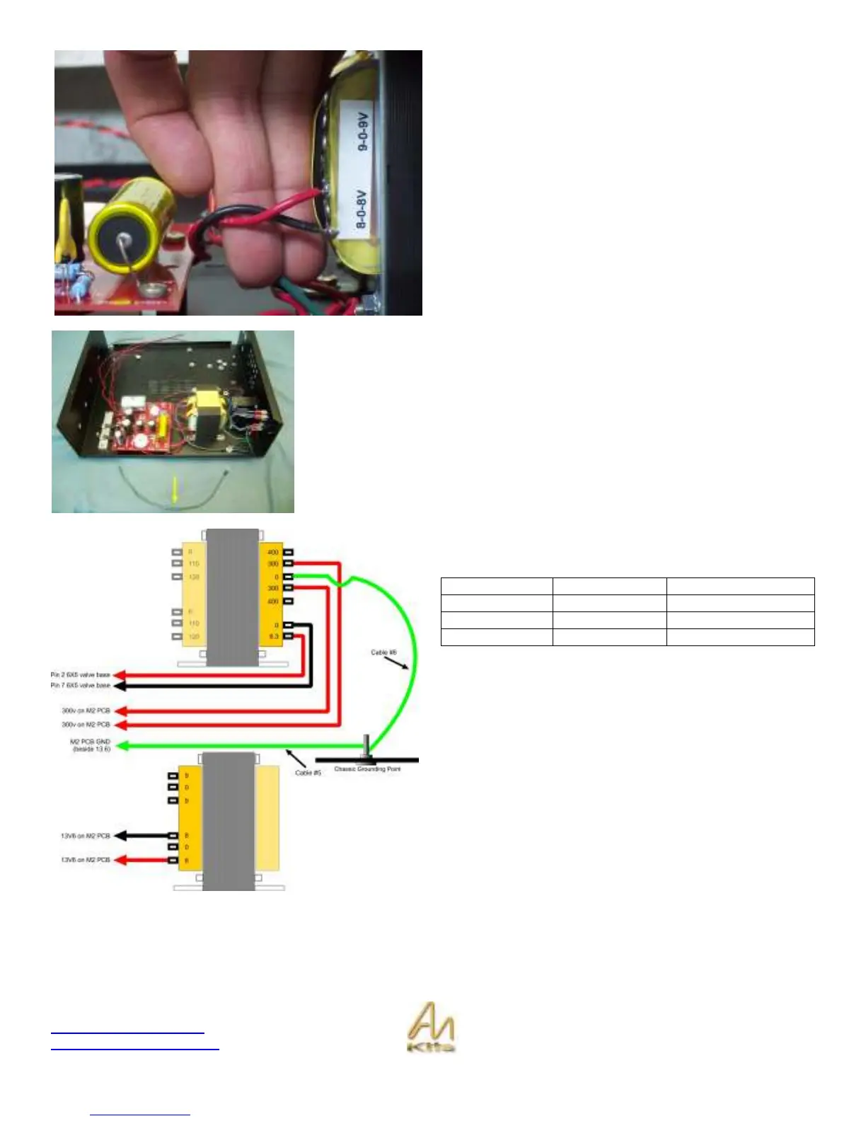
The third pair of wires is the Red/Black twisted pair that is
connected to the 13V6 on the M2 power supply board.
Note that the 0 tap is not used here.
The last wire for hookup in this section will be the long green wire with the GND
lug on one end found in your IEC Kit Bag- Secure the GND lug end on the M4
screw in the chassis and trim and solder from the top of the board the green wire
into the GND hole located near the 13V6 pads on the M2 power supply Board.
Now review your connections made in this section using the
graphic opposite and wiring table below.
Wire M2 PCB Mains Transformer
RED / RED 300v 300v 300 300
RED/BLACK 13V6 13V6 8 8
RED/BLACK Pin 2 & 7 6X5 0 6.3v
Check that you have made the connection between the
chassis GND lug and GND on the M2 PCB.
Check that you have made the connection between the
chassis GND lug and 0 on the mains transformer (i.e. the 0
between 300 and 300).