Copyright © 2007, 2008 AudioNote Kits
www.AudioNoteKits.com
audionotekits@rogers.com
Page 67
Section 10: Output Wiring
If you are building the Phono Version of the L2 Pre-amplifier then it may be a good idea to now switch to the L2 Phono
Board construction manual. If you choose, you could do that after wiring up the output - however, it may be more difficult
because you would have to route the phono board and additional wiring under the output wiring!
An AN-A (or AN-V), stereo paired wire has been supplied with your kit to connect the output of the line board to the output
RCA connectors. This is a very high quality cable and should be handled with care.
The ends of the stereo-paired cable have been pre-prepared to make installation easier. You will notice that at one end,
the screen wires and ground (white) are shorted together. This is the end that will connect to the analog output board.
RCA Connections
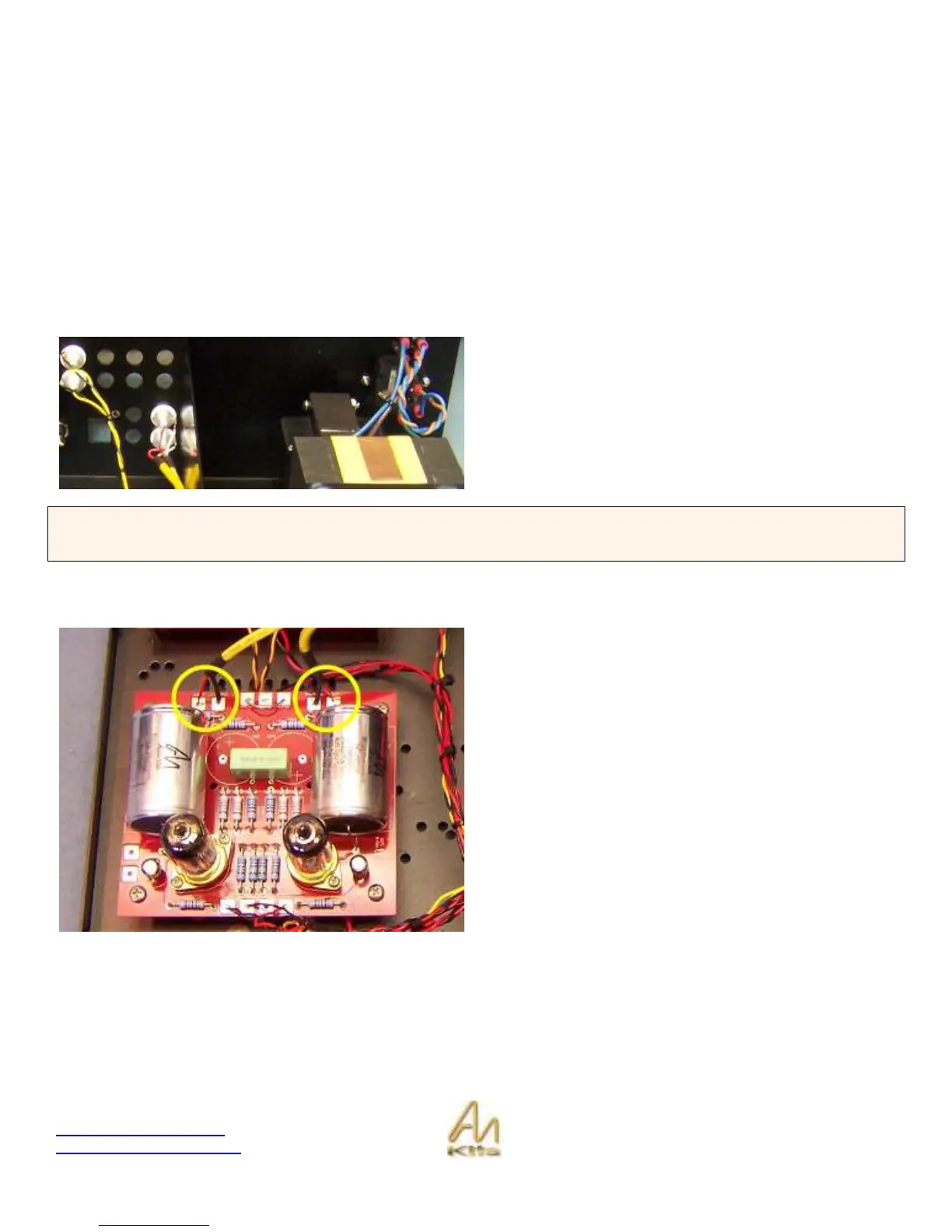
The Output RCA’s should be fitted on the bottom row
closest to the screen as shown opposite.
The end with just the red and white wires (i.e. no screen)
will connect to the output RCA. Solder white wires to the
appropriate RCA’s ground lug and the red wires to the
appropriate RCA’s center connection.
HINT: When connecting to the RCA’s – tin the RCA or apply solder. The center part of the RCA is where the red lead will
go – melt a little puddle of solder into the central part and then heat the puddle such that you can slide the tinned red lead
into it. Then tin the ground post and slide the white lead wire into position and solder.
Line Board Connections
The end with the thick ground wires will connect to the Line
Board.
The cable connected to the LEFT output connects to the
line board at LOUT (red) and LOUTGND (black/screen).
The cable connected to the RIGHT output connects to the
line board at ROUT (red) and ROUTGND (black/screen).