Copyright © 2007, 2008 AudioNote Kits
www.AudioNoteKits.com
audionotekits@rogers.com
Page 25
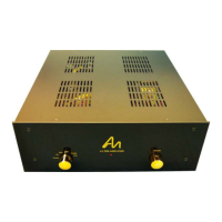
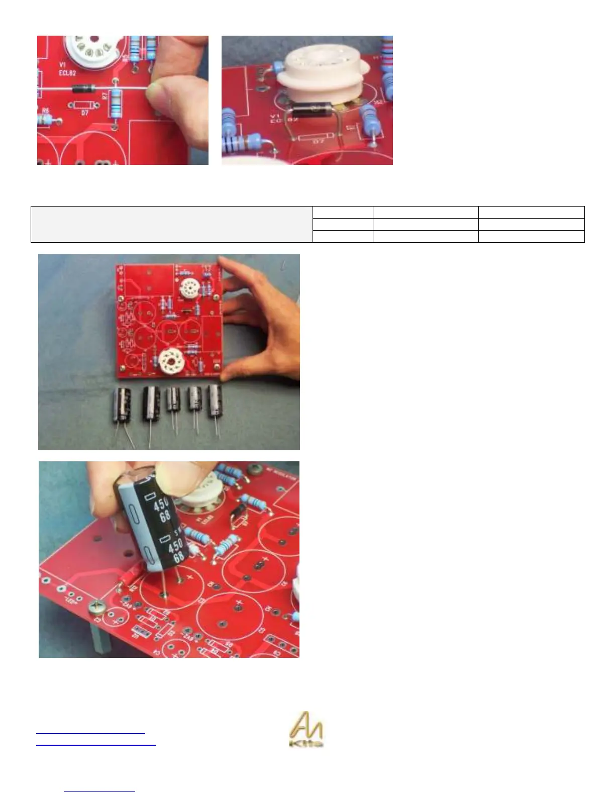
Here you can see the Zener diode
installed in the correct orientation.
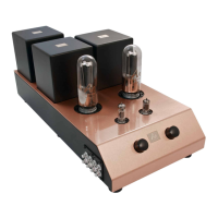
Electrolytic Capacitor Installation
1
2200uF 35V
C9
2
22uF 450V
C6 ,C7
Capacitors (Electrolytic)
Do not install C2 and C4 at this stage
2
68uF 450V
C3, C5
We are now going to install the Electrolytic Capacitors into
the power supply Board. Note that C2 and C4 will be
installed at a later stage.
Electrolytic Capacitor Lesson: An electrolytic capacitor is
a device that has a positive and a negative side to it. In
other words it MUST be installed correctly or it will basically
explode. Luckily the modern capacitors have a slow
explosion mode that will look like a dragon breathing fire.
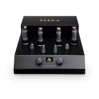
Let’s begin by installing C3.
You will notice that the capacitor has some markings on it -
a 68 for 68uF, a 450 for 450Volts, and a large strip down
one side which signifies the NEGATIVE side of the
capacitor.
You will notice on the stencil on the PCB that there is a +
designator on the board and you will need to orient such
that the + side is the opposite to the NEGATIVE stripe -
The electrolytic capacitor also has a longer lead on the
POSITIVE side.