Copyright © 2007, 2008 AudioNote Kits
www.AudioNoteKits.com
audionotekits@rogers.com
Page 55
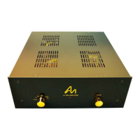
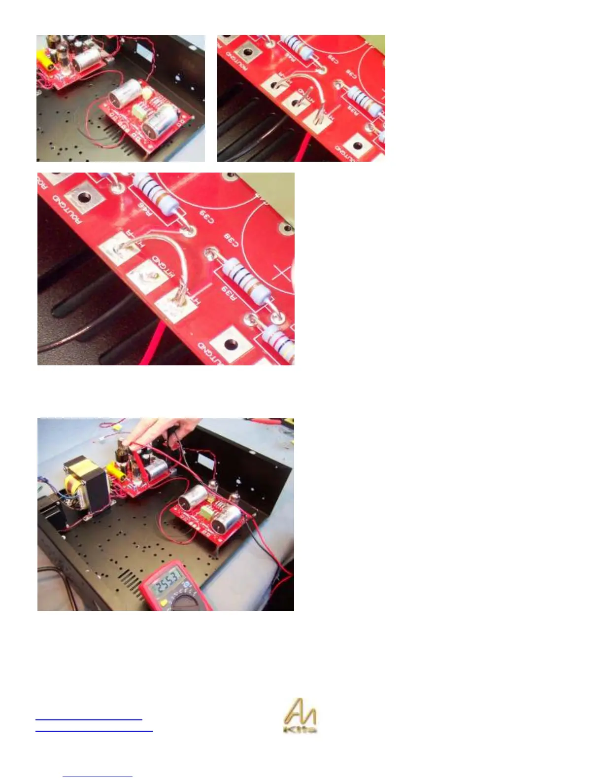
Locate the HT-R, HT-L and HTGND
pads - These are the pads that we will
be working with.
The HT wire will connect to one of the
HT pads and you will use some silver
wire to short between the two HT
pads.
The GND wire from the M2 Power
Supply connects to the HTGND pad.
Go ahead and solder the Red Wire from the B+ of the M2
power supply over to the HT R or HT Left along with the
silver bridge wire.
Then connect the Black GND wire from the M2 Power
supply over to the HTGND as shown in the picture to the
left.
Make sure that the HTGND does not come into contact with
the bridge wire.
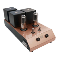
Electrical Test
Time for a DC voltage check - With the filaments and the
HT and GND connected to the L2 board we should do a
quick DC voltage test on the board.
Before installing the 12AU7 tubes, turn the unit on if you
are satisfied with your wiring and measure the High voltage
between the GND and the B+ on the M2 PS – Should be in
the 250-260v range.
You can then power down and install your 2 x 12AU7 tubes
into position.
Upon power-up check that your tubes are lighting up which
means our filament voltage supply is working fine.