GPIB ca bles are de signed so that they can be stacked if needed to con nect
mul ti ple instruments into your GPIB system.
When con nect ing in stru ments into a GPIB sys tem, ob serve the fol low ing
rules:
§
Con nect and dis con nect in stru ments from the bus only when the mains
power to all in stru ments in the sys tem is off.
§
As sign a unique GPIB ad dress to each in stru ment (de vice) on the bus.
§
De vices may be con nected in a star or lin ear con fig u ra tion (see Fig ure
72), or a com bi na tion of star and lin ear con fig u ra tions.
§
Do not at tach more than 15 de vices (in clud ing the con trol ler) to one bus.
§
Ca ble length be tween de vices must not ex ceed 2 me ters (6 feet).
§
One de vice must be at tached to the bus for ev ery two me ters (6 feet) of
ca ble.
§
To tal ca ble length must not ex ceed 20 me ters (66 feet).
§
At least two-thirds of the de vices on the bus must be pow ered up for
proper sys tem op er a tion.
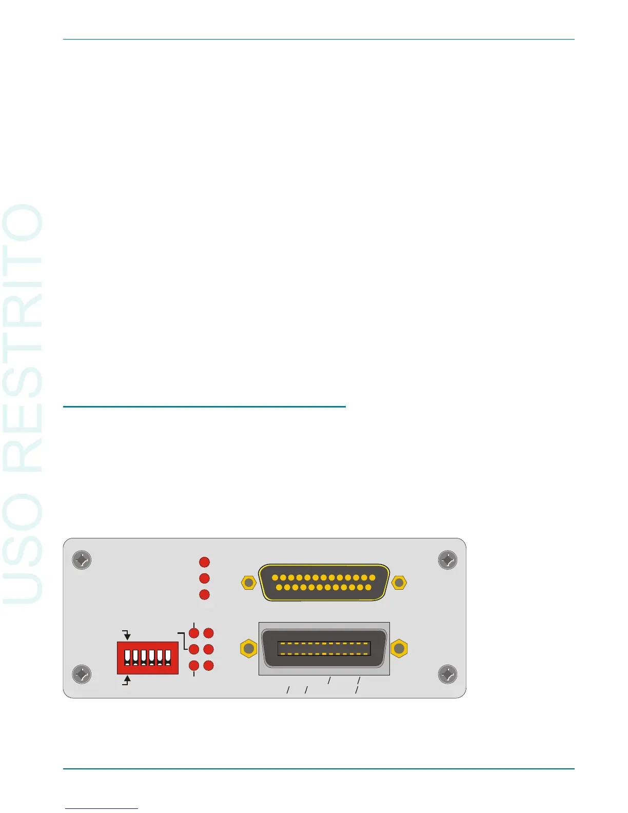
GPIB Address and Control Mode Switch
Like all de vices on a GPIB bus, the 2700 se ries in stru ment must be set to a
unique GPIB ad dress.
An ad dress se lect switch bank with six slide switches sets the GPIB ad dress
and the con trol mode. The switch is shown be low in Fig ure 73. The five
switches to the right of the bank set the 5-bit bi nary pri mary ad dress of the in -
stru ment. Le gal ad dresses are 0 through 30. Set each switch up for a bi nary 1
or down for a bi nary 0.
The GPIB Software Development Process Chapter 7: GPIB Configuration
Getting Started with Your 2700 Series Instrument 97
AUDIO PRECISION
INTERFACE BUS (APIB)
ERR
MAV
LA
RESET
RDNG
RDY
ADDRESSED
TA
SRQ
GPIB
GPIB
IEEE-488.2 (GPIB)
4
0
1
2 18 16
APIB
ADDRESS
RL0, PP0, DC1, DT1, C0, E2
SH1, AH1, T6, TE0, L4, LE0, SR1,