The Analog Signal Path
When the 2700 se ries con trol soft ware is launched, the de fault Page 1
workspace is loaded with two pan els, the An a log Gen er a tor and the An a log
An a lyzer, as shown in Fig ure 16. To re turn to this con fig u ra tion at any time,
click the New Test but ton. Pre vi ous set tings and data will be dis carded.
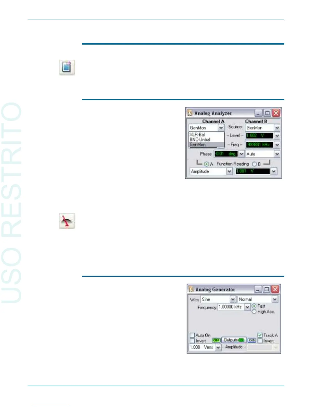
Analog Input Selection
The 2700 se ries has two chan nels of an a log in put that are ac cessed from the
An a log An a lyzer panel. Each chan nel can re ceive a sig nal from its front panel
bal anced or un bal anced con nec tor, or via an in ter nal path from the An a log
Gen er a tor. The Source fields on the An a log An a lyzer panel pres ent these
choices in a drop-down list. Go to the An a log An a lyzer by se lect ing Panels >
An a log An a lyzer or by click ing the An a log An a lyzer but ton. Choose
GenMon for each chan nel to se lect the in ter nal path.
Analog Generator Panel
Chapter 5: Quick Guides The Analog Signal Path
34 Getting Started with Your 2700 Series Instrument
Figure 17. Analog input selection via
Analog Analyzer Source drop-down lists.
Figure 18. Analog Generator, OUTPUTS
ON, CHB OFF.