See Chap ter 4 of the 2700 Se ries User’s Man ual for more in for ma tion about
the instrument in puts and out puts and the pan els as so ci ated with them.
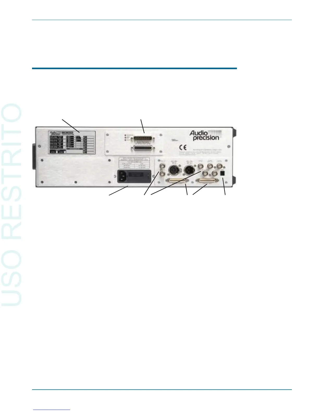
The 2700 Series Rear Panel
The SYS-2722 in stru ment rear panel, shown in Fig ure 12, in cludes the
power en try mod ule, sync and ref er ence in puts and out puts, par al lel dig i tal in -
put and out put, APIB in ter face con nec tors and the in stru ment con fig u ra tion
and se rial num ber la bels.
§
POWER ENTRY MODULE—this mod ule in cludes:
POWER CORD CONNECTOR—This is a standard grounded
connector for the mains power supply cord.
FUSE HOLDER/MAINS SUPPLY VOLTAGE JUMPER—Contains
the mains power fuse and the mains supply voltage configuration
jumper card. See Chapter 2.
MAINS SUPPLY VOLTAGE INDICATOR—The white tip of the
plastic indicator on the voltage configuration jumper card appears in
one of four small holes to show the mains voltage selection. See
Chapter 2.
§
SYNC and REFERENCE OUTPUTS
AES/EBU Reference
Master Clock Out
Transmitter Frame Sync Out
Receiver Frame Sync Out
The 2700 Series Rear Panel Chapter 3: Hardware Overview
Getting Started with Your 2700 Series Instrument 19