In the de fault con fig u ra tion, the An a log Gen er a tor panel is set for a 1 Vrms,
1 kHz sine wave, but the an a log out puts are dis abled. To turn on the out puts,
click the OUTPUTS OFF but ton near the cen ter of the panel. The but ton will
turn green, and you will hear re lays click in the in stru ment hard ware. The
Level me ters on the An a log An a lyzer panel will show ap prox i mately 1.000 V.
The Level me ters show the rms level of the sig nals at the an a log in puts.
The ste reo An a log Gen er a tor out puts can be in di vid u ally dis abled with the
CHA and CHB but tons next to the OUTPUTS field. Click on the CHB but -
ton. The but ton will turn gray, re lays will click in the in stru ment, and the
Chan nel B Level me ter on the An a log An a lyzer panel will in di cate a level of
0.000 V.
Now that we’ve suc cess fully routed a sig nal from the An a log Gen er a tor to
the An a log An a lyzer, we will perform some ba sic mea sure ments.
Using the Analog Analyzer
The 2700 se ries has two in de pend ent gen eral-pur pose an a lyz ers that can
per form mea sure ments on an a log sig nals. We will be us ing the An a log An a -
lyzer for the Quick Guide; the al ter na tive DSP Au dio An a lyzer is an anal y sis
tool avail able on the Dig i tal An a lyzer panel that of fers sim i lar anal y sis ca pa -
bil i ties. You can read about the both an a lyz ers in Chap ters 8 and 10 of the
2700 Se ries User’s Man ual.
The An a log An a lyzer is an an a log-do main real-time au dio an a lyzer, im ple -
mented in in stru ment hard ware. It pro vides con tin u ous read ings of sig nal level
and fre quency for both in put channels. It also al lows you to se lect a chan nel
and ap ply fil ter ing to it, and to mea sure pa ram e ters such as to tal har monic dis -
tor tion, phase, and so on.
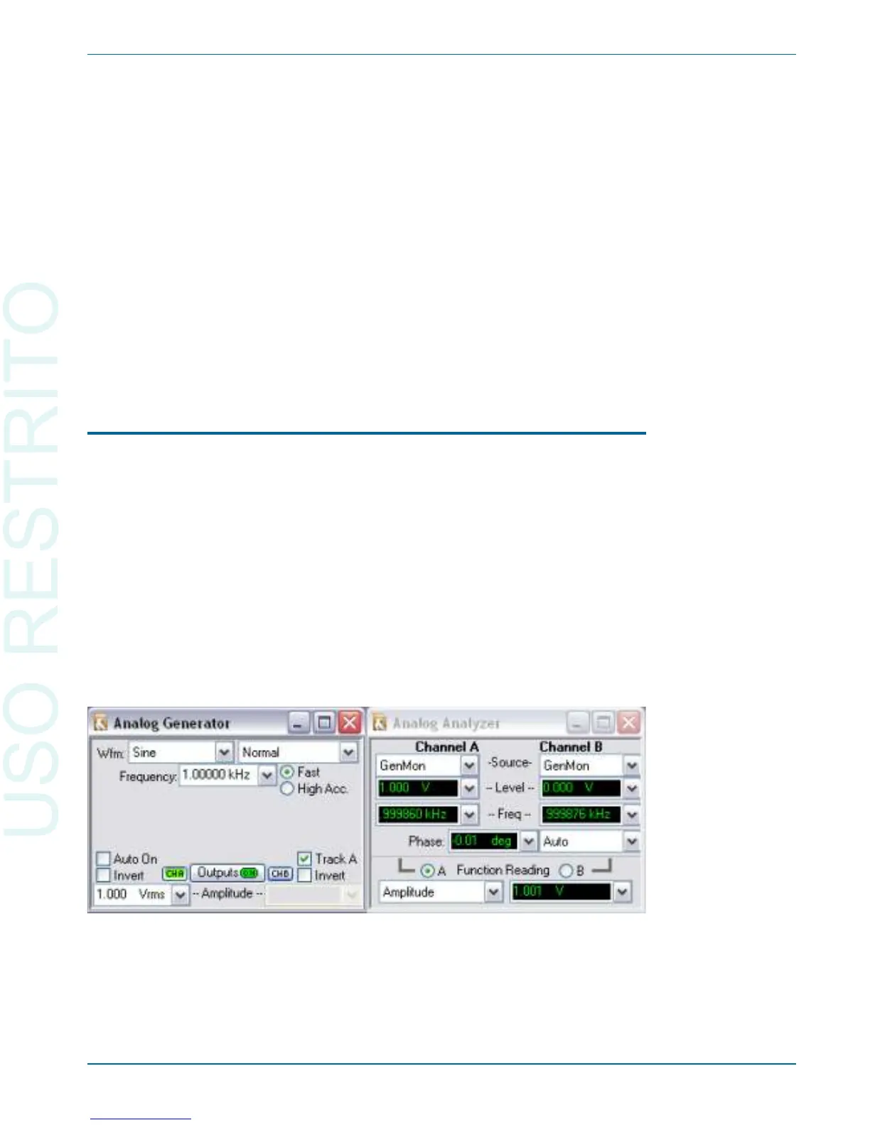
At this point, you should have the setup shown in Fig ure 19:
§
An a log Gen er a tor Chan nel A pro duc ing a 1 V, 1 kHz sine wave.
The Analog Signal Path Chapter 5: Quick Guides
Getting Started with Your 2700 Series Instrument 35
Figure 19. Analog Generator routed to Analog Analyzer inputs; generator Channel B is
set OFF in this illustration.