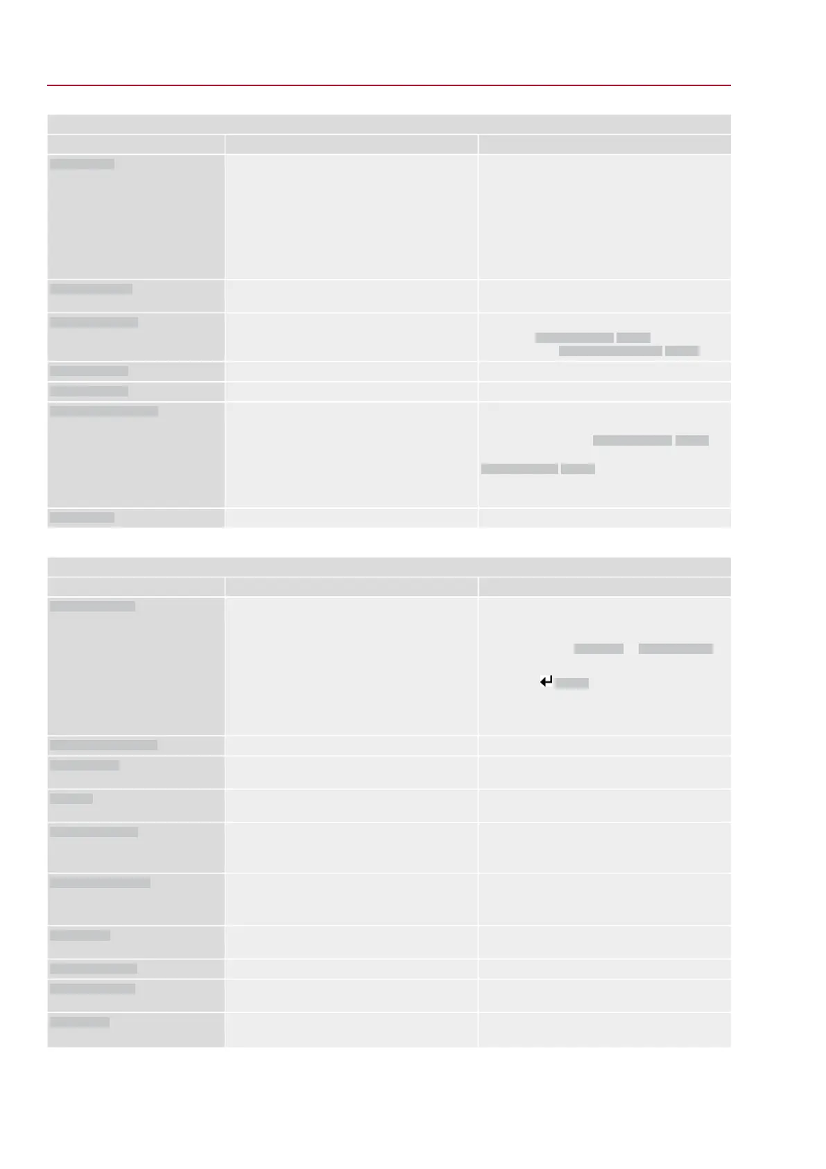
Warnings and Out of specification
RemedyDescription/causeIndication on display
Perform RESET or restart PVST.Partial Valve Stroke Test (PVST) was aborted or
could not be started.
PVST abort
●
Check movement at actuator.
●
Check parameter Reaction time M0634.
No actuator reaction to operation commands within
the set reaction time.
Wrn no reaction
Check parameter Wrn torque OPEN M0768, re-set
if required.
Limit value for torque warning in direction OPEN
exceeded.
Torque wrn OPEN
Check parameter Wrn torque CLOSE M0769, re-
set if required.
Limit value for torque warning in direction CLOSE
exceeded.
Torque wrn CLOSE
Execution of PVST (Partial Valve Stroke Tests) is
required.
PVST required
Maintenance is required.
Maintenance required
Table 30:
Faults and Failure
RemedyDescription/causeIndication on display
Drucktaster Details drücken, um Einzelmeldun-
gen zu sehen.
For a description of the individual signals, refer to
Manual (Operation and setting).
Collective signal 11:
Configuration error has occurred.
Configuration error
Drucktaster Details drücken, um Einzelmeldun-
gen zu sehen.
For a description of the individual signals, refer to
Manual (Operation and setting).
Collective signal 22:
Configuration error has occurred.
Config. error REMOTE
AUMA service
Press push button Details to display a list of indi-
vidual indications.
For a description of the individual signals, refer to
Manual (Operation and setting).
Collective signal 14:
Internal error has occurred.
Internal error
Perform one of the following measures:
●
Issue operation command in direction OPEN.
●
Set selector switch to position Local control
(LOCAL) and reset fault indication via push
button RESET.
●
Execute reset command via fieldbus.
Torque fault in direction CLOSE
Torque fault CLOSE
Perform one of the following measures:
●
Issue operation command in direction CLOSE.
●
Set selector switch to position Local control
(LOCAL) and reset fault indication via push
button RESET.
●
Execute reset command via fieldbus.
Torque fault in direction OPEN
Torque fault OPEN
Test/connect phases.
●
When connecting to a 3-ph AC system and with
internal 24 V DC supply of the electronics:
Phase 2 is missing.
●
When connecting to a 3-ph AC system: One of
the phases L1, L2 or L3 is missing.
Phase fault
●
Cool down, wait.
●
If the fault indication display persists after cool-
ing down:
-
Set selector switch to position Local con-
trol (LOCAL) and reset fault indication via
push button RESET.
-
Execute reset command via fieldbus.
●
Check fuses.
Motor protection tripped
Thermal fault
Check movement at actuator.No actuator reaction to operation commands within
the set reaction time.
Fault no reaction
Check device configuration:
Parameter Low limit Uspan M0832 must be less
than parameter Volt.level diff. potent. M0833.
Potentiometer is outside the permissible range.
Poti Out of Range
70
SQV 05.2 – SQV 14.2 / SQRV 05.2 – SQRV 14.2 Control unit: electronic (MWG)
Corrective action ACV 01.2 Non-Intrusive Profinet

 Loading...


