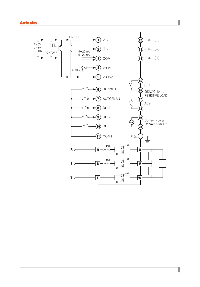
4. Connections
25
© Copyright Reserved Autonics Co., Ltd.
-|Transparent setting guide|-
※
1. Do not mix noise to input cable.
It is recommended to use shield cable, twisted cable as input cable for eective noise.
※
2. If there is possible to aect inductive noise,
it is recommended to use shielded cable at high-frequency power for eective noise.
※
3. DI input switch should be for low current and ON resistance should be max. 20Ω
(including cable resistance).
※
4. DI input terminals are COM, DI-1 to 3, RUN, AUTO.
※
5. For remote display unit option model,
use connection cable as our standard cable.
※
6. When connecting
⑥
,
⑪
, it operates as MANUAL. When connecting,
⑥
,
⑦
,
⑪
, it operates AUTO.
Voltage Input
External
VR
Voltage
Input
LOAD
LOAD
LOAD
 Loading...