EasyManua.ls Logo

Autronica AutroSafe - Cable Connection Overview

Autronica AutroSafe
93 pages
To Next Page IconTo Next Page
To Previous Page IconTo Previous Page
Loading...
Cable Connection Overview
asafeinstall_dgb, AutroSafe Interactive Fire Detection System, Release 4,
116-P-ASAFE-INSTALL/DGB, Doc-1004796-2, 2021-08-23, Autronica Fire and Security AS
Page 34
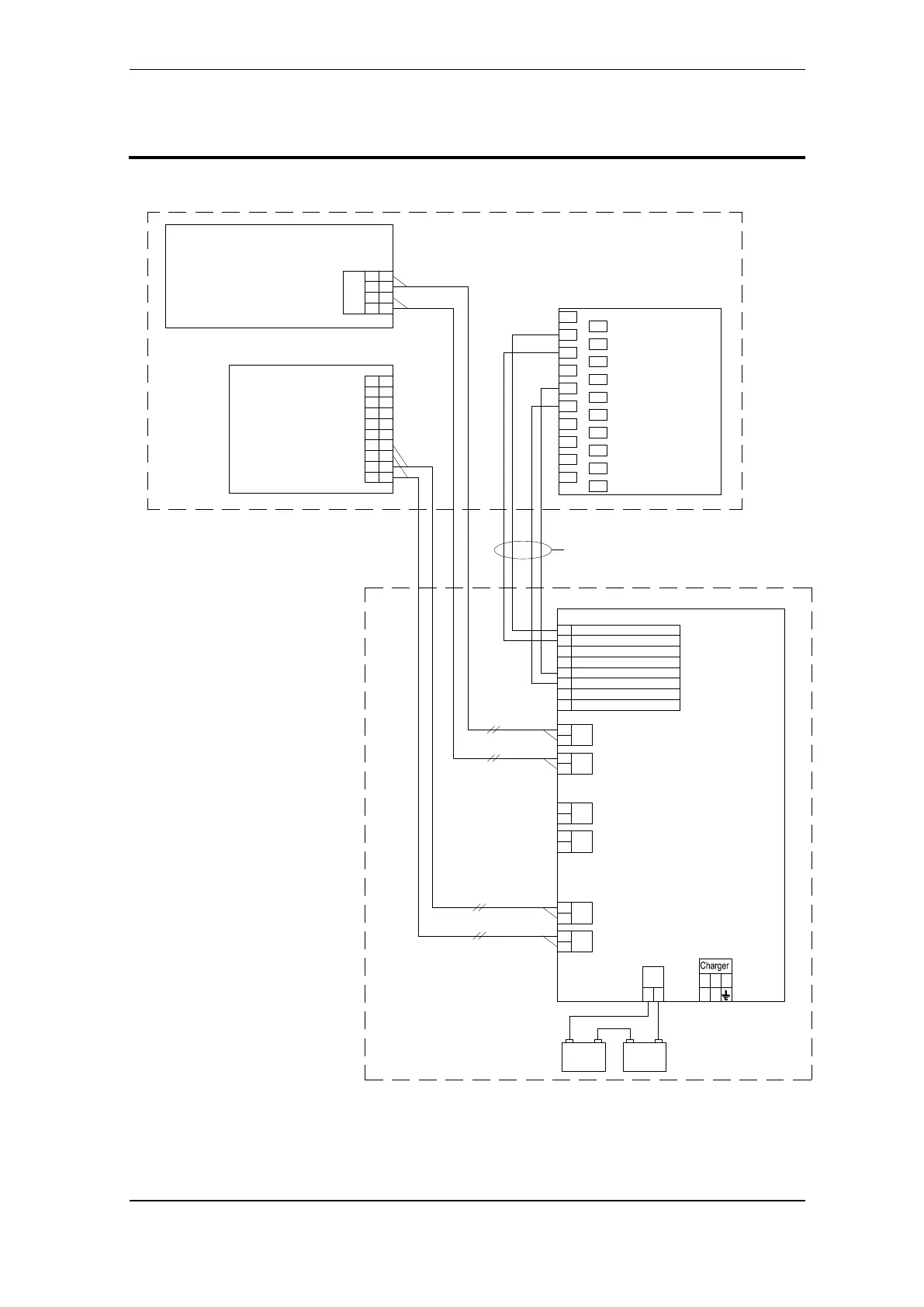
8. Cable Connection Overview
+
-
C1
+
-
C2
+
-
B1
+
-
B2
+
-
A1
+
-
A2
+
-
4
+
-
J18
3
2
1
BSA-400
+
-4
+
-3
2
1
Module
8
7
6
5
10
9
Power Board
5
6
7
8
1
2
3
4
AFB A
AFB A''
AFB CT A
AFB Earth Fault Sense
AFB B
AFB B''
AFB CT B
AFB Earth Fault Sense
+
-
Batt
+
-
1 2 3
13
15
17
19
5
7
9
11
1
3
14
16
18
20
6
8
10
12
2
4
TERMINAL
BLOCK
Cat.5
-- ++
12V 12V
Power Cabinet
BP-405
Fire Alarm
Control Panel
Controller Board
Power Supply
BS-420
BSF-400
BSS-310A
BSS-310A /
BSS-311
The cable connection overview
shows a redundant 24V cabling
between BSA-400 and BSF-400,
which is required for cabling
between two different cabinets.
If the 24V cabling is inside the same
cabinet, redundant cabling is not
required. Single cabling is thus
possible (for example, between
A1+/- and J18/1 / J18/ 2).
Power Supply
BPS-410

Table of Contents

Related product manuals