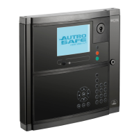
Do you have a question about the Autronica AutroSafe and is the answer not in the manual?
Provides information for the installation of AutroSafe Interactive Fire Detection System, Release 4.
Details systems with SW version 4.10.0 and later, including mixed environments.
Intended for Autronica Fire and Security trained service and technical personnel.
Lists technical marketing documentation for AutroSafe Interactive Fire Detection System, Release 4.
Crucial safety warnings, warranty disclaimers, and product usage guidelines for professional installation.
Discusses compliance with international and national safety standards for equipment installation.
Emphasizes following handbook instructions for safe operation and ensuring updated documentation is used.
Recommends using the latest firmware/operating system for optimal system performance.
Outlines requirements for system design, installation, and testing for safe operation.
States that product modifications are not allowed and disclaims liability for any injuries or damage.
Explains safety words (NOTICE, CAUTION) and their associated symbols for important information and hazards.
Provides information on product certificates, standards, and approval bodies, mentioning NFPA 70/72.
Covers recycling and disposal guidelines, adhering to WEEE Directive and environmental standards.
Specifies panel placement according to local regulations and consultation with the fire brigade.
Refers to separate datasheets for information on environmental requirements for AutroSafe equipment.
Recommends a mounting height of approximately 175 cm for optimal readability of the panel display.
Discusses the EN-54 approved power cabinet STX and BPS-410 Power Unit, selection based on project needs.
Introduces chapters covering the mounting of various panels, cabinets, and power units.
Provides step-by-step instructions for mounting the BS-420/BC-420 panel, including panel removal and drilling.
Details the procedure for mounting the BS-430 Operator Panel, including drilling and fastening.
Guides the mounting of the BU-BV-420 Repeater Panel, including dipswitch settings.
Explains how to mount BV-110/BU-110 Loop Panels, including text foil insertion and cable connections.
Details mounting the STX Range Power Cabinet, advising to follow supplier manuals and notes on placement.
Covers mounting the BPS-410 Power Supply Unit, including dipswitch settings and calibration.
Provides instructions on how to correctly insert text foils into panels for identification purposes.
Illustrates the positioning and dimensions of cable inlets/outlets for BS-420/BC-420 and BU-BV-420.
Shows cut-out dimensions for flush mounting Repeater Panel BU-BV-420 in a wall.
Shows cut-out dimensions for flush mounting the Operator Panel BS-430 in a wall.
Details power consumption for STX Power and BPS-410, including current ratings and inrush peak.
Lists current consumption for various system units like BS-420, BC-420, BU-BV-420, BS-430, and BSF-400.
Refers to technical specifications in datasheets for current consumption of various loop units.
Discusses power consumption of Phoenix Ethernet Switches used in network solutions like AutroNet.
Provides an overview of internal cable connections for BS-420/BC-420, showing cable types and ports.
Details AL_Com+ and Multifunction Serial Port connections on the Controller Board BSA-400 and BSL-310.
Explains the ribbon cable connection from the Serial Port to the terminal block L1.
Tabulates the overview of Multifunction Serial Port connections from J3 to terminal block L1.
Refers to a separate datasheet for information on cabling to AutroSafe Controller Rack BC-440.
Illustrates the internal earth cabling for the system for EMC compliance.
Introduces the chapter on connecting external cables and refers to appendix for detail.
Specifies safety precautions before connecting cables, including power off and fuse removal.
Recommends security measures for Ethernet ports and panel placement to prevent unauthorized access.
Details the requirement for a two-pole disconnect device in mains wiring for servicing.
Covers AutroFieldBus connections to terminal blocks and connectors, including cable requirements.
Explains how to connect network cables for AutroNet, covering star and ring topologies.
Details RS-485 connection requirements, including cable type, resistance, and length.
Provides RS-422 connection details, including schematic of port equivalent and protection.
Outlines RS-232 connection requirements to terminal block L1, including cable type.
Details 24V power connections to the Controller Board BSA-400A, showing redundant and single cabling.
Provides links to manuals for Power Cabinet STX and safety notes for BPS-410 mains power.
Introduces information on mounting and removal of I/O modules, noting pre-mounted internal modules.
Shows the front view of an I/O module when mounted on a rail, indicating screw terminals.
Covers general notes on mounting order, power off, and the physical mounting procedure for I/O modules.
Details the procedure for removing I/O modules using a screwdriver, ensuring the panel is not powered.
Reiterates the safety measure of ensuring the mains power is OFF before connecting cables.
Informs about AutroSafe User Documentation providing data sheets for I/O modules.
Explains the Dual Safety concept with Primary and Secondary Systems and the need for AutroKeeper BN-180.
Provides rules of thumb for connecting Loop Driver Modules to I/O stacks and panels in Dual Safety configurations.
Illustrates connections using AL_Com+ only for both primary and secondary systems with short cable runs.
Shows connections using AL_Com+ and AutroFieldBus for longer distances and protocol converters.
Explains the role of AutroKeepers BN-180 and BSD-321 in Dual Safety Systems for loop access.
Details the pin connections for the AutroKeeper BN-180 module.
Explains the dipswitch settings on BN-180 to determine if it's Primary or Secondary.
Introduces the Log Menu for system events and the duty to register them in a Control Journal.
Lists steps for monthly maintenance, including log review, detector checks, and panel inspection.
Outlines the annual inspection process for the entire system, including key tests and checks.
Provides safety precautions and guidelines for replacing fuses, emphasizing using identical replacements.
Recommends annual capacity testing and replacement of batteries every 4 years.
Stresses the importance of verifying the entire system after commissioning for proper operation.
Advises service personnel to physically disconnect or disable safety-critical systems during maintenance.
States that service and maintenance for SIL2 approved systems follow proof test intervals from the certificate.
Provides a table to record contact information for the local service representative.
Displays a detailed layout of the Controller Board BSA-400A, showing connectors and switches.
Shows the BSA-400 board installed inside the Fire Alarm Control Panel BS-420.
Describes the BSA-400 Controller Board as the main CPU controlling system functionality and its communication ports.
Lists and describes the function of each internal LED on the BSA-400 board.
Details the Power Input Connector J18 on the BSA-400 and its connections to the Power Board BSF-400.
Explains the function of the two-stage push button reset (S5) for controlled and hard resets.
Describes the USB host ports for connecting printers or memory sticks, including load limitations.
Details the Multifunction Serial Port Connector J3, its connections to terminal block L1, and its role in AutroFieldBus.
Explains AutroFieldBus short-circuit detection, topology, and cable types, with specific connection details.
Details the dipswitch settings on S6 for RS-232, RS-422, and RS-485 configurations.
Outlines the CAN Bus termination dipswitch settings on switch S7.
Covers RS-485 ribbon cable connections to terminal block L1 and switch settings for S6/S1.
Details RS-422 connections via ribbon cable and switch settings for S6/S1, including port schematics.
Explains RS-232 connections via ribbon cable and switch settings for S6/S1.
Describes the Serial Debug Connector J21 and its interface parameters for programming.
Details the AL_Com+ Connector J5 and its connections to the Communication Module BSL-310.
Lists the connectors and descriptions for the LCD backlight on the BSA-400.
Describes the Ethernet ports (RJ-45), their status LEDs, and cable compatibility.
Details the BPS-410 Power Unit 24VDC/10A, its components including Power Board BSF-400.
Shows a diagram of the Power Board BSF-400 with its various connectors and components.
Describes the BSF-400 as a power monitor, controller, and communication interface, detailing its features.
Provides an example power block diagram showing connections between BSA-400 and BSF-400.
Specifies recommended cable parameters and battery size for BSF-400, with no minimum power requirement.
Details battery input specifications, fuses, and maximum current draw for BPS-410 and BSF-400.
Explains temperature-controlled battery charging, charge current control, and low voltage warnings.
Details how to start the system from battery using button S2, with troubleshooting for voltage issues.
Explains configuration of the BSF-400 board using dipswitches S5/S6 and rotary switches for address.
Provides detailed tables for dipswitch settings on S5 and S6, explaining their functions and comments.
Lists and describes the connectors on the BPS-410, including power outputs and their properties.
Explains the fault relay watchdog function on the BSF-400 board and the meaning of LEDs.
Describes the process of measuring battery impedance and the criteria for high resistance faults.
Explains power output protection by electronic and regular fuses, and battery input protection.
Discusses configuration and diagnostic outputs when the power module is part of an AutroFieldBus network.
Explains how to use the BPS-410 power supply in standalone mode via dipswitch settings.
Details the mounting procedure for the obsolete BP-405 Power Cabinet, including battery installation.
Lists the obsolete power cabinet BP-405 and power unit BPS-405, detailing their contents and specifications.
| Brand | Autronica |
|---|---|
| Model | AutroSafe |
| Category | Measuring Instruments |
| Language | English |
