Home
Autronica
Measuring Instruments
AutroSafe
Page 66 (Internal LED Indicators on BSA-400)
Autronica AutroSafe - Internal LED Indicators on BSA-400; Power Input Connector J18 on BSA-400
93 pages
Manual
To Next Page
To Next Page
To Previous Page
To Previous Page
Loading...
Appendix A - Cont
roller Board BSA_
400A
asafein
stall_dgb
,
Au
troSafe Interacti
ve Fire Detection Syst
em, Release 4,
116
-P-ASAFE-INSTALL
/DGB, Doc-1004796-2, 2021-
08
-
23
,
Autronica Fire a
nd Security AS
Page
66
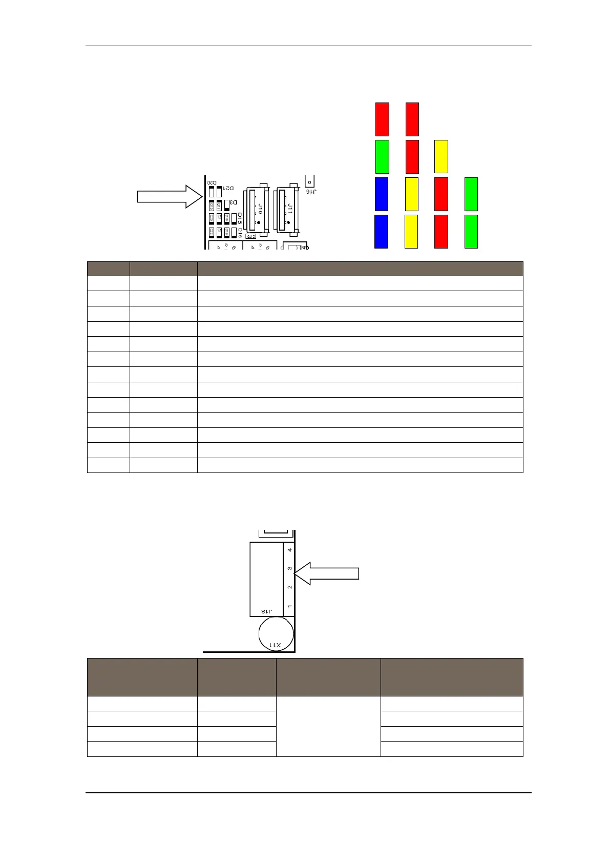
15.4
Internal LED I
ndicators
LED
Colour
Function
D1
Yellow
SD
-Card activity
indicator
D2
Yellow
USB Boot Time Resc
ue upgrade in progr
ess
D3
Yellow
System fault LED, ON w
hen system is lock
ed in system fault
D13
Green
AutroFieldBus TX
D15
Green
NA
D16
Green
Power indicator
D17
Red
AutroFieldBus RX
D18
Red
NA
D19
Red
Serial Port activity
indicator
D20
Red
System reset 5V
D21
Red
System reset 3,3V
D22
Blue
System heart beat
D23
Blue
NA
LED Colour Fu
nction
15.5
Power Inp
ut Connector J18 (sc
rew terminal)
Connector J18 on
Controller Board
BSA-400
Description
Connection to Power
Board BSF-
400
J18.1
+24V DC In 1
Interconnection
A1 +
J18.2
0V In 1
A1 0V
J18.3
+24V DC In 2
A2 +
J18.4
0V In 2
A2 0V
D20
D21
D13
D17
D23
D2
D22
D1
D19
D16
D18
D15
D3
BSA-400
J18
BSA-400
65
67
Table of Contents
Main Page
Default Chapter
3
Table of Contents
3
1 Introduction
7
About the Handbook
7
Hardware / Software
7
The Reader
7
Reference Documentation
8
2 Safety
9
Important Safety Information
9
National Standards and Regulations
10
Technical Documentation
10
Recommendations for Latest Available Firmware and Operating System
10
System Design, Installation, Commissioning, Testing and Validation
11
Modifications to the Products
11
Safety Notices
12
Compliance with Standards and Directives
12
Standards NFPA 70 and NFPA 72
12
Environment Compatibility
13
Recycling
13
Disposal
13
3 Pre-Installation
14
Location
14
Environmental Requirements
14
Mounting Height / Space Requirement
14
4 System Units - Overview
15
Power Supplies
17
5 Loop Panels - Overview
18
6 Mounting Instructions
19
Introduction
19
Mounting Fire Alarm Control Panel BS-420/Controller BC-420
20
Mounting the Operator Panel BS-430
22
Mounting Repeater Panel BU-BV-420
23
Mounting Loop Panels (BV-110 and BU-110)
25
Mounting Power Cabinet STX Range
26
Mounting Power Supply Unit BPS-410
27
Inserting Text Foils
28
Cable Inlets / Outlets
29
Cut out Dimensions for Flush Mounting in a Wall
30
Repeater Panel BU-BV-420
30
Operator Panel BS-430
31
7 Power Consumption
32
Mains Power
32
STX Power
32
Bps-410
32
System Units
32
Loop Units
32
Phoenix Ethernet Switches
33
8 Cable Connection Overview
34
9 Connecting Internal Cables
35
Overview - BS-420 / BC-420
35
Bs-420 / Bc-420
36
Al_Com+ Connection on Controller Board BSA-400
36
Al_Com+ Connection on Communication Module BSL-310
36
Multifunction Serial Port Connection on Controller Board
36
Bsa-400
36
Multifunction Serial Port Connection on Terminal Block, List L1
37
Multifunction Serial Port Connection Overview - BSA-400
37
Internal Earth Cabling
38
10 Connecting External Cables
39
Introduction
39
Before Connecting Cables
39
Cyber Security
39
Mains Wiring - Two-Pole Disconnect Device
39
115/230VAC Voltage BPS-410
40
Autrofieldbus Connections
40
Connections to BS-420/BC-420 - Terminal Block (List 1)
40
Connections to Connector J2, Power Board BSF-400
41
Example of the Interconnection of Several Power Cabinets
41
Connection of Network Cables (Autronet)
42
Autronet Redundant Star Topology
42
Autronet Single Star Topology
43
Autronet Ring Topology
44
Connection to Controller Board BSA-400
45
Common Earth Connections
45
RS-485 Connections to Terminal Block, List L1
46
RS-422 Connections to Terminal Block, List L1
46
RS-232 Connections to Terminal Block, List L1
46
Power Connections
47
Connections to Controller Board BSA-400A
47
Connections to Power Board BSF-400
48
Power Connection Overview
49
Mains Power Connections
50
Power Cabinet STX
50
Power Supply BPS-410
50
11 Installing I/O Modules
51
Introduction
51
Front View of I/O Module
51
Mounting / Removing I/O Modules
52
General
52
Mounting
52
Removing
53
Before Connecting Cables
53
Data Sheets - I/O Modules
53
12 Dual Safety Installation
54
Dual Safety System Overview
54
Rules of Thumb
54
Example 1: Connections Using Al_Com+ Only
55
Example 2: Connections Using both Al_Com+ and Autrofieldbus
56
Connections Overview
56
Connections - Autrokeeper BN-180
58
Switch Settings - Autrokeeper BN-180
58
13 Cable Specifications
59
14 Service and Maintenance
60
Introduction
60
Monthly Maintenance
60
Annual Service and Maintenance
61
Fuse Replacements
62
Battery Replacement and Maintenance
62
Testing
62
Safety Measures During Commissioning and Maintenance
63
SIL2 Approved Systems
63
Contact Information Local Service Representative
63
15 Appendix A - Controller Board BSA_400A
64
Circuit Board Layout
64
Location Inside Fire Alarm Control Panel BS-420
65
Description
65
Internal LED Indicators
66
Power Input Connector J18 (Screw Terminal)
66
Two-Stage Push Button Reset (S5)
67
USB Ports (J10, J11)
67
Multifunction Serial Port Connector J3 - Autrofieldbus and Fault Relay
68
Autrofieldbus Connections
69
Ribbon Cable Connector BSA-400 to Terminal Block L1
69
Multifunction Serial Port Dipswitch Settings - Switch S6
70
CAN Bus Termination Dipswitch Settings - Switch S7
70
RS-485 Connections
71
Ribbon Cable Connector BSA-400 to Terminal Block L1
71
Switch Setting - Switch S6 and S1
71
RS-422 Connections
72
Ribbon Cable Connector BSA-400 to Terminal Block L1
72
Switch Setting - Switch S6 and S1
72
Schematic of Port Equivalent
72
RS-232 Connections
73
Ribbon Cable Connector BSA-400 to Terminal Block L1
73
Switch Setting - Switch S6 and S1
73
Serial Debug Connector J21
73
Al_Com+ Connector J5
74
LCD Backlight Connector J17
74
Ethernet Ports (RJ-45 Connectors)
75
Ethernet Straight through Cable
75
16 Appendix B - Power
76
Power Unit BPS-410
76
Power Board BSF-400
76
Description
77
Power Block Diagram - Example
77
Batteries
78
Power Unit BPS-410
78
Battery Charging
78
Button S2 - Start on S2 on Standby Source
79
Configuration Settings
80
Dipswitch Table - S5 and S6
81
Connector Description BPS-410
82
Fault Relay Watchdog J26
83
Battery Resistance Measurement
84
Electronic Fuses
84
Power Outputs
84
Battery Input
84
Part of an Autrofieldbus Network
85
Power Unit BPS-410 as Standalone
85
17 Appendix B - Fault Messages Power Board BSF_400
86
17. Appendix B - Fault Messages Power Board
88
18 Appendix C - BP_405 (Obsolete)
88
Mounting Power Cabinet BP-405 (Obsolete)
88
Power Cabinet and Power Units
91
Power Cabinet BP-405 (OBSOLETE)
91
Power Unit BPS-405 (OBSOLETE)
91
Related product manuals
Autronica AUTROSAFE 4
51 pages
Autronica AutroSafe BSD-340
27 pages
Autronica Autroprime 2
152 pages
AUTROSAFE Self Verify BS-310
3 pages
AutroSafe Maritime Gas Detection
84 pages
Autronica Autroprime
82 pages
Autronica Autro Safe BS-310
64 pages
AutroVoice miniVES Series
156 pages
AutroGuard Multicriteria Protector V-430 Series
126 pages

 Loading...