Avid S6 Installation Guide10
About Custom Module Configurations
You can customize the arrangement of modules in many different ways. After you have assembled the system you will use the
Touchscreen (see Figure 2) to tell the system where you have installed which modules, choosing arrangements as available in the
Settings > Surface > Config screens. Use this information to determine your module layout before proceeding with the system as-
sembly.
M40 and M10 Plus systems also support Display Modules, which can be installed above channel sections (but not above Master
or Automation Modules).
The Producers Desk option consists of two chassis (Small or Large) that include a special Inlay panel that spans both chassis. The
inlay provides space for you to position computer displays and a keyboard. You can also add a Fader Module (or other) to either
or both chassis of the Producers Desk. If your system includes a Producers Desk option, decide whether you want to install it at the
far left end, far right end, or between other chassis in the frame.
For now, decide where you want your fader strips to be in relation to the master section modules, and where you want the Producers
Desk (if your system includes one), then proceed to Part II, “Frames.”
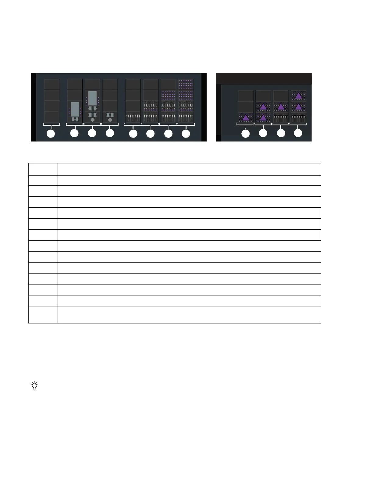
Figure 2. Supported arrangements of modules per chassis (Display Modules not shown)
Supported Module Configurations
Legend Module Arrangement per Chassis
1 None (empty chassis, for Master Meter Modules, Fill Panels and/or the Producers Desk option)
2 Master Module in slots 1 and 2
3 Automation Module in slot 1 and Master Module in slots 2 and 3 (standard master section configuration)
4 Automation Module alone in slot 1
5 Fader Module alone in slot 1
6 Fader Module in slot 1, Process Module in slot 2
7 Fader Module in slot 1, Process Module in slot 2, Knob Module in slot 3 (standard channel configuration)
8 Fader Module in slot 1, Process Module in slot 2, Knob Modules (2x) in slots 3 and 4 (standard channel configuration)
9 Expand Zone (Attention Track Knob Module) alone in slot 1
10 Expand Zones (2x) in slots 1 and 2 (M40 system only)
11 Fader Module in slot 1, Expand Zone in slot 2
12 Fader Module in slot 1, Expand Zones (2x) in slots 2 and 3
Additional Module Arrangements are available that include Expand Faders, Master Joystick Modules, and Master Post
Modules
The location of the Producers Desk in the frame, as well as the presence of any Fader Modules in the Producers Desk, affects
placement of the Ethernet switch(es) and PSUs. For guidelines and examples, see “If Your System Includes a Producers Desk”
on page 35
1
2 3 4
5 6 7 8 9
10 11 12
 Loading...
