4-/5-Gas Measuring Instruments Unit AVL 4000
5-10 Service Manual
5.4 Power Supply Unit for 4-/5-Gas Measuring
Instruments Unit
• Disconnect connector P1 (3-pin) and P2 (9-pin).
• Remove the entire unit by undoing the 4 screws on the carrier plate. (It is a good idea
to use an offset screwdriver, Phillips screw)
• Mount the new unit and reconnect the cable.
5.5 Power Supply Board
• Remove the complete 4-/5-gas measuring instruments unit.
• Unscrew the 4 Phillips screws from the base plate.
• Disconnect the mains power supply and the connection cable to the main board.
• Install the new power supply board
• Reconnect the plugs.
5.6 O
2
Sensor and NO Sensor
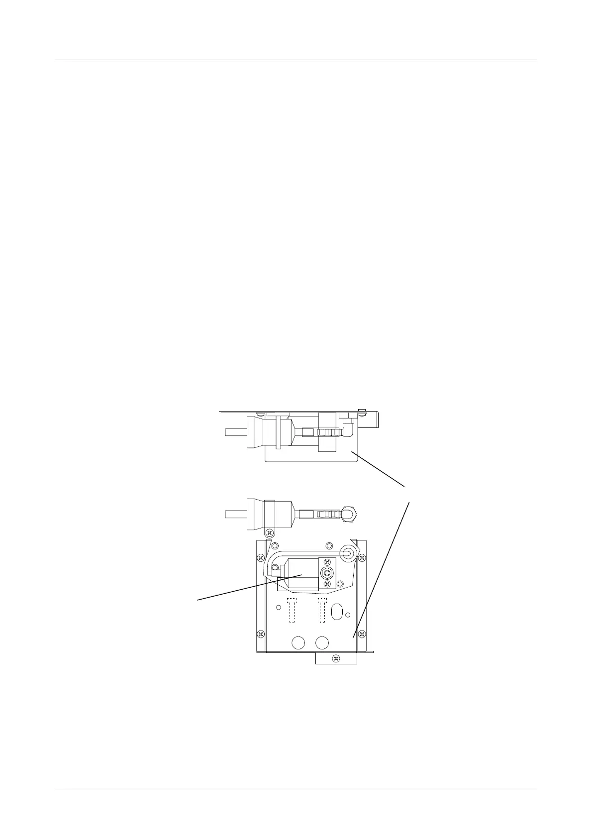
Fig. 5-7
The O
2
sensor is mounted on the rear panel and is easily accessible.
It is protected by a metal cover which is secured to the rear panel by 4 Phillips screws.
For connection cable to the measuring system and hose lines, see Layout of Pneumatics.
With the NO (5 gas) option, the NO sensor is also mounted in the O
2
sensor housing.
Rear view
View from above
O
2
sensor
O
2
sensor housing
 Loading...