Opacity Measuring Chamber 4000 AVL 4000
7-8 Service Manual
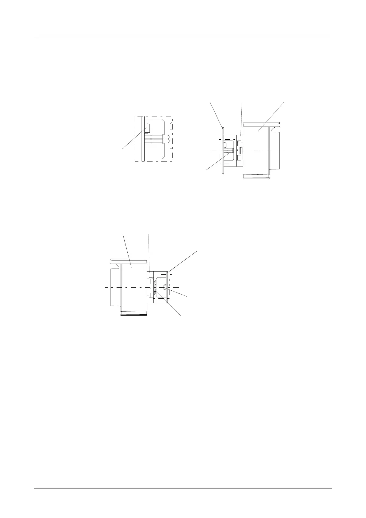
7.4.4 Transmitter and Detector Unit
Transmitter unit (BO2140)
Fig. 7-9
Detector unit (BO2141)
Fig. 7-10
7.4.4.1 Checking the Light Sources (green LEDs) and the Receiver
See service screen.
The light source voltage must be between 3.5 and 4.5 V.
7.4.4.2 Checking the Reference Receiver
See service screen.
The voltage must be between 2.5 and 4.5 V.
Reference detector
EO0148
LEDs
EO0147
Transmitter board
BB0777
Optical pickup
YM3191
Flow channel
RM0146
Flow channel
RM0146
Optical pickup
YM3192
Receiver board
BB0778
Detector
EO0148
Lens
MO0102
 Loading...