4000 Evaluation Unit
Service Manual 4-51
4.23 Internal Cabling
The internal cabling has been minimised by using connectors that are directly soldered
into the pcbs.
Most of the remaining cables in the evaluation unit therefore are the mains cables with
protective earth wiring, the connection cables to the peripheral devices (power supply
unit, display, softkeys, printer, fan), the ribbon cables connecting the main board to the
optional pcbs and the connection lines to the 4-/5-gas section.
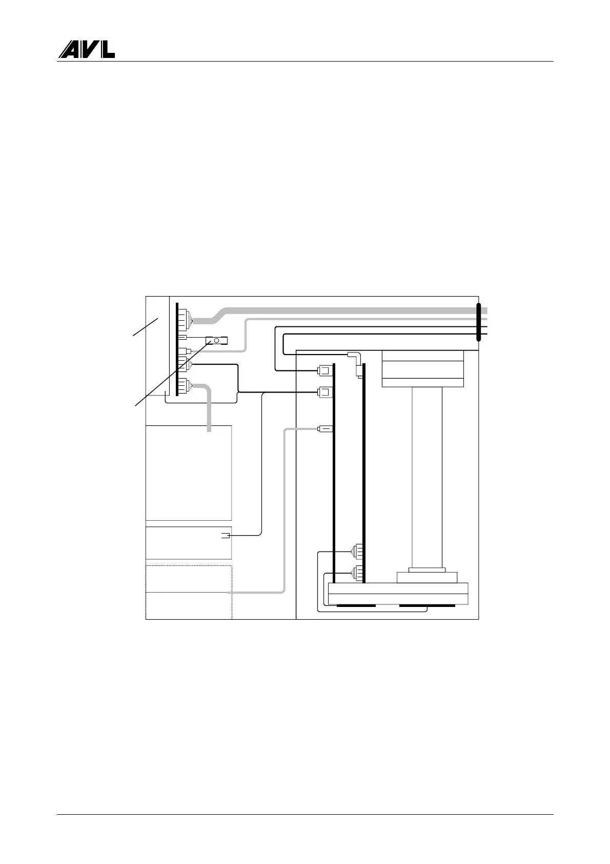
The figure below shows the wiring of the 4-gas section, i.e. how the 4-gas measuring
instruments unit, pneumatics modules, O
2
sensor and pneumatics board are connected to
each other and to the evaluation unit.
Fig. 4-4
X8
Mains 230V/50 Hz
pressure
RS232
direct voltage
X3
X6
X5
Earth contact
plug
Control Board
Solenoid valve
24 V
Pump
230 V / 50 Hz
O
2
sensor
Fan
24V
two-speed
Meas. chamber
Analogue board
Control board
NO sensor
(optional)
 Loading...