4000 Opacity Measuring Chamber Type A
Service Manual 6-19
• Position the sensor so that it extends to approximately the middle of the gas inlet
bore.
• Glue the sensor into the groove at the gas inlet.
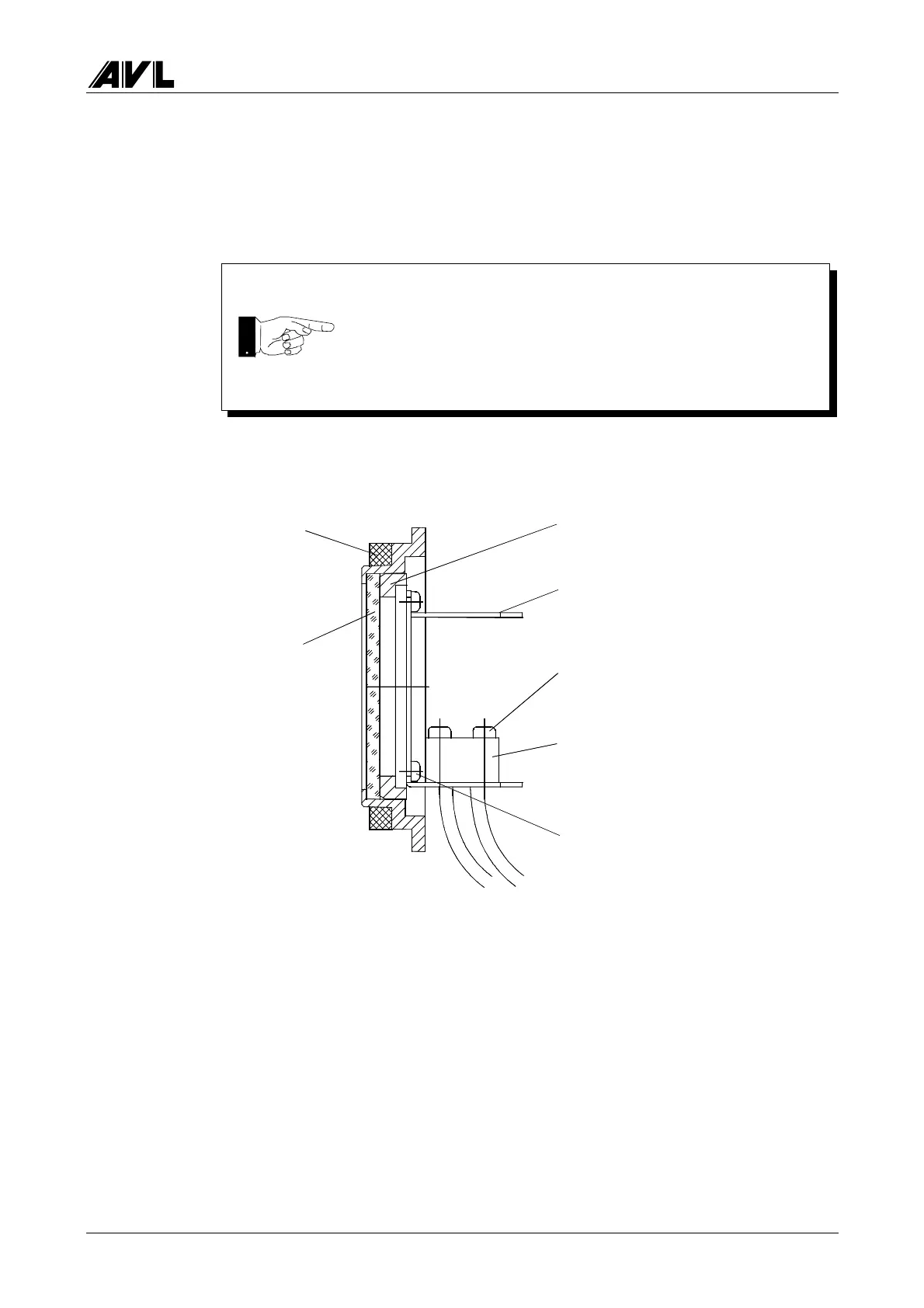
6.9 Lamp Module (BO1135)
Fig. 6-27
• Undo the 4 PT screws.
• The entire cover plate can now be removed from the module housing.
• Disconnect the 4 plugs at the rear of the light source.
• Unscrew the lamp socket to change the lamps.
Halogen lamp 12 V, 5 W EL0209
Do not get glue on the inside surface of the bore.
Seal ring
YM2721
Protective glass
MO0046
Spacing ring
RM0123
Mounting bracket
YM2806
4 self-tapping screws
DS1009
2 lamp sockets
BV1666
2 PT screws
NS0046
 Loading...