Opacity Measuring Chamber Type A AVL 4000
6-12 Service Manual
4
7
Fig. 6-19
Half-shell 1 RM0113
Half-shell 2 RM0114
Silicon seal RM0120
6.5 Fans
• Dismantle the opacity measuring chamber as described in section 6.4 Dismantling the
Opacity Measuring Chamber.
One fan is mounted in half-shell 1 and the other in half-shell 2 - the two fans are
identical.
• To dismantle them, undo the two screws on the back of the fans.
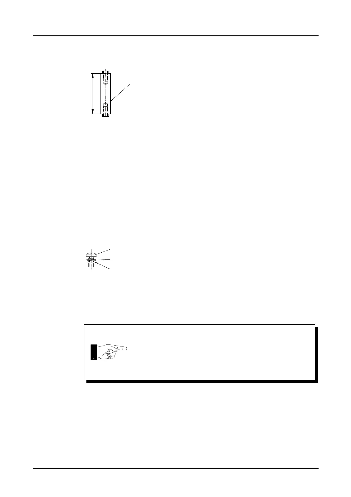
Fig. 6-20
Fans EI0188
12 VDC, incl. connection cable and connector
Stud bolt C YM2681 2 pcs.
Oval-head screw M3x6 DS0160
Spring washer DZ0526
Washer DZ0245
Draw the connection cable through the hole in the half-shell when
reassembling.
Reconnect the cables when re-mounting the fans.
Always carry out a function check after fitting a new fan (see
Operating Manual).
 Loading...