4000 Opacity Measuring Chamber Type A
Service Manual 6-11
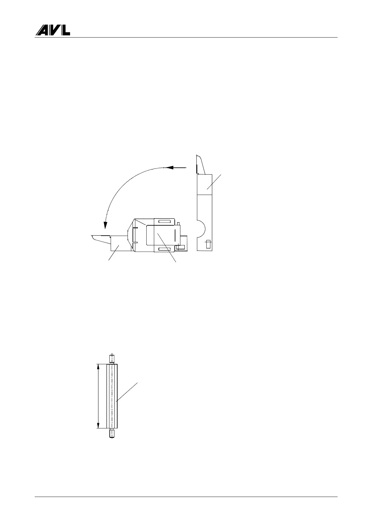
The measuring chamber should now be standing upright in front of you with the exhaust
gas outlet (half-shell 1) facing you.
• Fold open the optical modules.
• Carefully pull the half-shells apart.
• Make sure that the axles of the optical modules remain in the mounting on the gas
outlet side.
• When you have completely separated the two half-shells, you can let half-shell 1 lie
horizontally.
Fig. 6-17
If you want to separate the two half-shells completely, disconnect the following cables
from half-shell 2:
− protective conductor (Faston connector on the purging air and heating block)
− fan cable
− heating cable
The remaining 4 bolts do not need to be removed:
7
0
Fig. 6-18
Pull apart,
fold down
Half-shell 2
Half-shell 1 Optical module
Stud bolt D YM2682 2 pcs.
 Loading...