Evaluation Unit AVL 4000
4-62 Service Manual
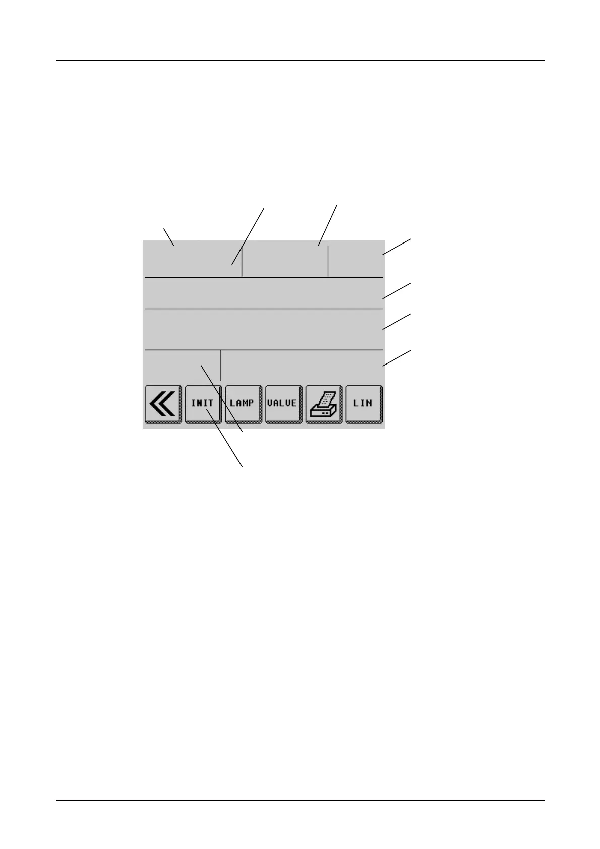
4.25.5 Diesel - Opacity Measuring Chamber 4000
Error diagnostics menu for opacity measuring chamber
Fig. 4-8
Opacity signal
The opacity signal is the displayed value calculated from system voltages RC and RF:
displayed value = (RC HIGH - RC LOW) × f(RF) f(RF)…correction factor
Please use the system voltage values to assess the function.
Gain factor
This factor depends on the optical conditions in the opacity measuring chamber and
dictates the LED intensity gain (0.5…1.8).
OPACITY SIGNAL SYSTEM VOLTAGE LAMP
2.685 V 1.2 A
VALVE SWITCH TIME POSITION
1.7 s CALIBRATION
TEMPERATURE
MEAS. CHAMB. INLET MEAS.HEAD SYSTEM
101° C 85° C 20° C 25° C
LINEARITY DATE TIME SW version
0.5 % 30/01/99 16:30
Opacity signal
(depending on LEDs,
photoelectric cell and
gain setting)
System voltage
(4 values)
Change lamp status
by pressing LAMP
(Lamp A, B, A/B, OFF)
Change valve setting
by pressing VALVE
Measured temperatures
System info:
date, time,
software version
silicon serial number
(main board and
chamber adapter)
Linearity display
Start linearity test by pressing LIN
Re-initialisation of measuring system
Gain
factor
 Loading...